In order to use the ISO C procedure for asymmetric teeth, we need to create a calculation method that is capable of determining two factors, which we will here refer to as YeFa and YeSa, equivalent to the abovementioned factors YFa and YSa and applicable in Equation 1.
With reference to Figure 1, note the asymmetric tooth HCAK'I,' with the driving side on the left; note, also, the symmetric tooth HCDKI, both sides of which are identical to the driving side of the asymmetric tooth.
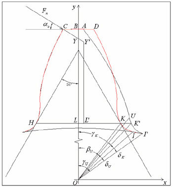
Figure 1--Comparison of symmetric (HCDKI) and asymmetric (HCAK'I') tooth forms.
The methodology of this study is based on two hypotheses, the validity of which will be proven upon analysis of the results: the critical section HK' of the asymmetric tooth is assumed to be at the same distance from the center of the wheel as the critical section HK, determined on the symmetric tooth by the sixty-degree wedge; we define as axis of the asymmetric tooth the perpendicular to segment HK', passing through point L' of its center line.
The profile curvature radius, ρF , at the critical point H, is obviously identical for both symmetric and asym-
metric teeth.
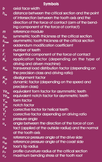
In conclusion, according to Equation 2, the form and notch factors of asymmetric teeth differ from those of symmetric teeth only inasmuch as the values of sFn differ, equal respectively to HK' and HK, and that of hFa , equal respectively to L'Y' and LY.
Considering that, for admissible ∆α values (Ref. 4) of the tooth asymmetry, segment L'Y' is only slightly lower than the corresponding segment LY, we have deemed it opportune in this study to assume the value hFa = LY also for asymmetric teeth, for the benefit of greater accuracy. (In fact, an approximated, rounded-up value is assumed for the arm, which is conventionally defined in procedure ISO C, of the bending component of the force of contact.)
Therefore, factors YeFa and YeSa for asymmetric teeth can be determined by replacing sFn in Equation 2, with the corresponding value sFnas, equal to the length of segment HK' of Figure 1.
Calculation Software
The first thing the user must do in order to use the calculation software, created using the Matlab language, is to enter all the input data necessary for determining the characteristics of the toothing, namely, the number of teeth, the tool’s geometric characteristics (module, pressure angle of the two sides, addendum, tip radius), and the addendum modification and addendum reduction coefficients. The user must determine all the geometric parameters (characteristic radius, thickness, etc.) of both the asymmetric tooth being calculated and the symmetric tooth of reference, as described above. The coordinates of the intersection points between the involutes and the respective tooth fillet profiles are thus identified through the appropriate iterative cycles (for example, point U for the coast side of the asymmetric tooth in Figure 1); thus, the profiles of the two teeth, the symmetric and the asymmetric one, are fully defined.
Once the coordinates of point U are known, it is possible to calculate the amplitude of angles βU , δU and γU shown in the figure (I’ is the starting point of the trochoid on the inside circumference). Through the application of widely used procedures (Ref. 5), the coordinates of point H are determined, as well as the thickness sFn = HK of the critical section of the symmetric tooth. Through another iterative cycle, the coordinates of point K' are determined, from which we can obtain the value of angle δK'.
At this point, we determine the thickness of the critical section of the asymmetric tooth sFnas :

where: OL = y-axis, previously calculated, of point H;

Using the value of sFnas provided by Equation 3, we calculate the form and notch factors, YeFa and YeSa , for asymmetric teeth, through which we can finally determine the maximum bending stress, σF, at the root of tooth.
Results and Verification
As specified in the previous paragraphs, certain hypotheses and approximations were assumed in order to fine-tune the calculation methodology of this study. In order to assess the validity of such methodology, we have deemed it opportune to make a comparison—through numerous combinations of the tooth parameters—between the bending stress values calculated using FEM methodology and the values calculated using the modified ISO C procedure.
The test campaign highlights, in particular, how the stress values for both symmetric and asymmetric teeth calculated using the FEM methodology are, as already known for symmetric teeth, generally lower than the values calculated using the ISO C methodology. This depends mainly on the fact that the ideal stress calculated using the FEM methodology in the most highly stressed point of the tooth fillet of the driving side (traction area) takes also into account, with great accuracy, the compression resulting from the radial component of the force of contact between the teeth.
The most important point that we can make after having analyzed the results is the fact that the differences between the stress values calculated using the two methodologies are not directly dependent on the tooth’s degree of asymmetry. It is possible to verify the above by the data in Table 1, which shows, for some of the case studies: the number of teeth z, the pressure angle of the driving side α01, the pressure angle of the coast side α02, the degree of asymmetry ∆α = α02–α01, the percentage difference ∆σ% ISO / FEM between the stress calculated using the ISO methodology (modified in the case of asymmetric teeth) and the stress values calculated using the FEM methodology (the symmetric tooth case studies are highlighted in the table).
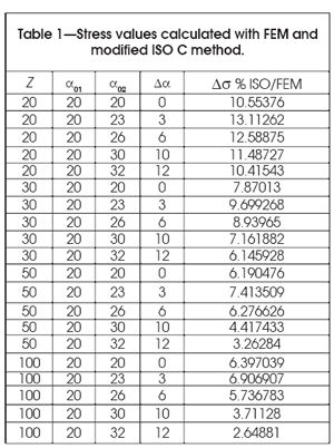
The values in Table 1, particularly those of ∆σ% ISO / FEM, make it possible to propose the procedure referred to in this paper for determining the equivalent form and notch factors for asymmetric teeth and, consequently, the use of the ISO C methodology also for this type of teeth.
By using this methodology for a wide range of case studies, we were able to obtain a large number of calculation results. Figure 2 shows a graph—of the several obtained by varying z, x and ρa0—which indicates, in relation to the degree of asymmetry ∆α, the percentage of stress reduction ∆σ% versus symmetric teeth (x = addendum modification coefficient; ρa0 = tool tip radius).
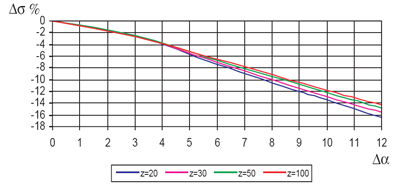
Figure 2--Percentage decrease of stress calculated using modified ISO C (x=0; ρa0=0.25).
Using graphs like the one shown in Figure 2, the designer of asymmetric teeth can obtain a direct estimate of the expected stress reduction, with respect to traditional symmetric teeth.
Finally, as further proof of the validity of the calculation method proposed in this paper (the “modified” procedure ISO C), we have evaluated, always in relation to the degree of asymmetry, the difference D between the above said stress reduction ∆σ% and the corresponding stress reduction calculated using the FEM methodology. Also in this case, we have drawn numerous graphs (one example is shown in Figure 3), which show a very slight difference, in fact, lower than 2–3%.
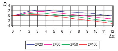
Figure 3--Difference D between the percentage stress reduction calculated using modified ISO C method and using FEM (x=0; ρa0=0.25).
In other words, for evaluating the stress reduction obtainable through the use of asymmetric teeth, the estimate provided by the proposed procedure does not differ greatly from the one provided by the FEM procedure.
Conclusions
The calculation method created in this study, used for the dimensioning of asymmetric teeth, allows the user to determine valid “equivalent” form, YeFa, and notch, YeSa, factors; the software created ad hoc simplifies this calculation.
Using the equivalent factors, we are able to estimate the maximum bending stress at the tooth root with an approximation, rounded up, which is very close to that commonly considered acceptable for symmetric teeth.
In brief, the results of this work clearly show that gear designers may conveniently use the widely used ISO C procedure for verifying the bending stress in the case of asymmetric teeth.
References
1. Di Francesco, G. and S. Marini, “Structural Analysis of Asymmetric Teeth : Reduction of Size and Weight,” Gear Technology, Sept/Oct 1997, Elk Grove Village IL. U.S.A., 1997.
2. Di Francesco, G., M. Linari and S. Marini, “Sistema di modellazione ad Elementi Finiti per Ingranaggi a Fianchi Asimmetrici,” XXXII Convegno Nazionale AIAS, September 3–6, 2003, Università di Salerno.
3. Di Francesco, G., S. Marini, G. Grasso and C. Clienti, “Asymmetric gear wheel thermographic analysis,” Colloque Photomecanique 2004, étude du comportement des matèriaux et des structures, Albi, 2004.
4. Di Francesco, G. and S. Marini, “Asymmetric gear wheel design: determining the bending stress in relation to the degree of asymmetry,” TMT 2004, September 15–19, 2004.
5 Salamoun, C., and M. Suchy, “Computation of helical or spur fillet,” ASME Paper No. RM4, ASME/AGMA/IFTOMM International Symposium, Oct. 1972.
Giulio di Francesco is a professor of machine design at Università degli Studi di Roma “La Sapienza” and at Università di Roma Tre, where he specializes in the study of gears. He has more than 32 years of scientific teaching and research experience. He has written more than 60 professional technical publications and is a consultant to major automotive and other companies. He holds a number of patents at the Italian and international levels.
Stefano Marini is a professor of machine design at Università degli Studi di Roma “La Sapienza” and at Università di Roma Tre. His research interests include gears, structural analysis, elastic behavior of metals, design methodologies and mechanical fatigue. He has written more than 40 technical papers and is a consultant to major industries.
 In the design of transmission gears, it is often necessary to increase bending strength while maintaining load carrying capacity or increase the load carrying capacity while maintaining bending strength.


