The differing left-and right-flank base circles result in unsymmetrical tooth profiles in helical gears (see Fig. 4).
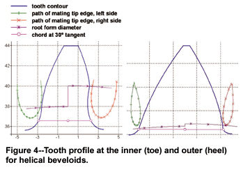
Manufacturing by means of a rack-type cutter results in a tooth root cone angle equal to the
cone angle δ. The addendum angle is designed in a manner that avoids tip edge interference with the meshing gear and to achieve the maximum possible transverse contact ratio. As a result, we have a different tooth height across the face width.
Due to the geometric design limits for undercut and pointed teeth, the face width decreases with increasing cone angle. Sufficiently well-proportioned gears are possible up to a cone angle of about 15°.
Microgeometry. The pairing of two conical gears generally results in a point-like tooth contact. Outside this contact, spacing (separation) occurs between the tooth flanks. The object of gear modification is to reduce spacing (gaping) in order to obtain a planar and even contact.
Exact calculation of the tooth flank is possible through applying the rule of the common normal, as shown in Figure 5 (Ref. 5).
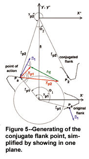
To this end, a flank point P1 with the radius rP1 and corresponding normal vector n1 is generated on the original flank. We get the speed vector vP1' through:
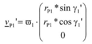 (4)
(4)
For the point generated on the mating flank, the radial vector rP2
 (5)
(5)
and the velocity vector vP2" apply.
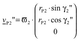 (6)
(6)
The angular velocities result from the gear ratio:
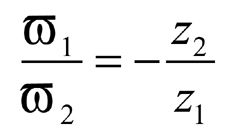 (7)
(7)
The angle γ is iterated until the rule of the common normal
 (8)
(8)
is fulfilled. The point of action Pa found is rotated through the angle Φ2
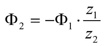 (9)
(9)
around the gear axis and thus the conjugate flank point P2 is obtained.
Gear set arrangements. Beveloids can be installed in the following axis configurations:
-parallel axes,
-intersecting axes and
-skewed axes.
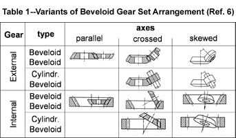
Due to the fact that selection of the cone angle does not depend on the shaft angle, pairing is also possible with cylindrical gears. Beveloids can be produced as external or internal gears, as shown in Table 1, so a whole matrix of pairing options results, and the designer is provided with a high degree of flexibility (Ref. 6).
Load capacity calculation. Certain conditions provided, analytical calculation methods for involute spur gears, such as ISO 6336, DIN 3990 or AGMA C95, can be used for sufficiently accurate determination of the load capacity of beveloids in intersecting axial arrangement. This is, however, only possible if the tooth contact is linear. Since the tooth contact of most beveloid sets without flank modifications is point contact, flank modifications must bring about approximate linear contact.
The tooth profile changes across the face width, and consequently load capacity in the individual face sections across the face width changes. The main influences on tooth root capacity change across the face width in opposite directions, which are shown in Table 2.
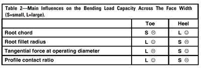
Homogenous tooth root capacity across the face width is to be aimed at. The influences on flank capacity also vary across the face width, as shown in Table 3.

The load capacity of the tooth center section can thus be seen as representative for the entire gearing. All geometric gear parameters are determined in the tooth center. Only the center distance must be converted into a substitute center distance as and is obtained by adding up the pitch radii.
 (10)
(10)
Contact pattern quality can be assessed on the basis of the width factors (e.g., KHΒ and KFΒ in DIN/ISO), which are to be determined as precisely as possible on the basis of the contact conditions. Load capacity calculations according to the finite element method are of a higher quality and to be preferred
over analytical methods.
Beveloid Gear Sets in Automatic Car Transmissions
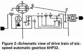
Macrogeometry. Based on experience with the design of marine and robot gears, beveloid gear sets for a new range of 6-speed automatic transmissions have been designed. But in car transmissions, macrogeometry is more restricted, and the demands regarding low-noise design are much higher. For the smallest possible transmission error to be attained, the gear was designed with a pressure angle αn= 17.5° and a helix angle Β=29.5°. This gives a transverse contact ratio of &Epsilonα=1.7 on the coast side and 1.8 on the drive side. The face contact ratio &EpsilonΒ is 1.89 on the coast side and 1.63 on the drive
side.
Due to the relatively wide helical angle, the transverse pressure angle αt on the drive side is 15.3° and on the coast side 23.9°. For pairing with
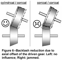
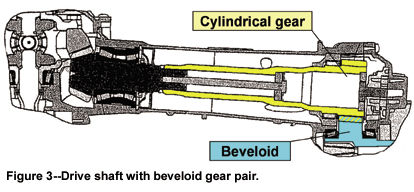
a shaft angle of 8°, combination of a beveloid gear (input) with a cylindrical gear (output) was chosen. This resulted in a root angle of 8.6° on the beveloid gear. This combination was necessary because the output gear must be axially displaceable over a relatively wide range for adjustment of the bevel drive pinion on the output shaft. If two beveloid gears were used, axial displacement would result in the tooth backlash being too heavily affected, as is shown by Figure 6. Selectable face width is limited by the limits for pointed teeth on the heel and the undercut on the coast side on the toe of the beveloid gear.
For maximum load capacity to be achieved on the drive side, a relatively large undercut was
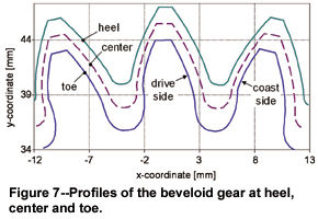
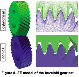
accepted on the toe of the coast side, with such an undercut being unusual for cylindrical gears. The profiles of the beveloid gear for the inner edge (toe), the center and the outer edge (heel) are shown in Figure 7. Figure 8 shows the FE model of the gear set. This model was used in the FE program PERMAS for calculating precisely the stresses resulting from the contact conditions and the load capacity of the gear set (Ref. 7).
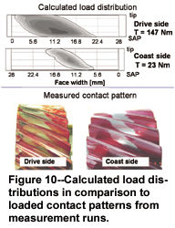
Microgeometry. The point contact of the beveloid gear set is a major problem when it comes to realizing design targets. This unfavorable contact behavior negatively affects load capacity and at low load results in high travel deviations, which cause an inordinately high noise level. The mismatch dimensions (ease-off) determined by means of a tooth contact analysis are shown in Figure 9. On the unmodified gear, we have both crowning and profile twist, which clearly differ for the drive flank and coast flank. Figure 9 also shows the spacing (gap) on the potential contact lines of a mesh position; they illustrate the crowning and tilt caused along the contact line. The effects of spacing (contact gap) on flank pressure were analyzed by a load distribution calculation with the program LVR (Ref. 8). In the computation, the gear set was approximately modeled as a parallel axis drive, and contact gap was considered as flank topology on one gear of the gear set. This permitted adequate representation of the contact conditions, which were verified by a comparison of calculated load distributions with contact patterns measured.
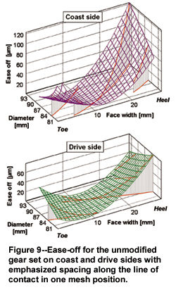
Figure 10 shows LVR-computed load distributions and the contact patterns for the same loads. To significantly improve contact conditions through enhanced contact width, topological flank modifications were computed for the cylindrical gear of the gear set.
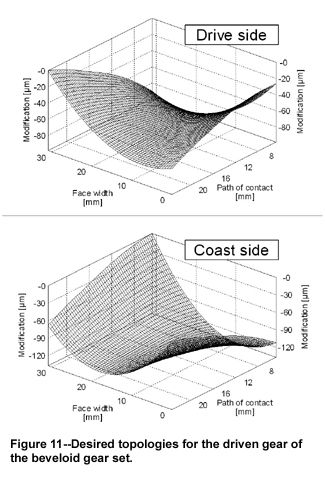
The object was to compensate as far as possible the existing spacing (gap) without completely eliminating the crowning. Particular attention was paid to the compensation of the profile twist, which causes the diagonal contact pattern and, like the crowning, prevents a full contact. The topologies shown in Figure 11 were generated on test gears on a 5-axis KAPP grinding machine and tested for comparison with the unmodified gears.
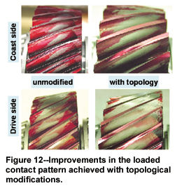
The contact pattern was significantly improved, as shown in Figure 12. Gear noise was also clearly reduced with the topologically modified gears. In the following sequence, the topologies were converted into conjugate topologies for the beveloid gear and defined as the specification for batch-production methods. Optimum topology has been very closely realized in the batch production launched in the meantime. In fine adjustment of the topology, great attention was paid to the resulting noise excitation, which needed to be improved--especially for partial loads.
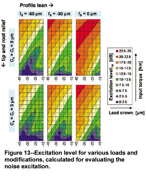
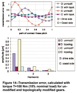
With the present fine geometry, it has been possible to achieve the low noise level aimed at, which corresponds with that of a well designed set of helical gears. Compared to the unmodified variant, a noise reduction of more than 10 dB was achieved in critical speed ranges, especially under partial-load conditions. Assessment of the excitation level was also carried out with the program LVR, which was used in serial computations to determine transmission error for various loads and modifications (Ref. 8). Using the diagrams of the excitation levels calculated on the basis of the transmission error, it was possible to assess the efficiency of individual corrections. Figure 13 shows an example of the diagrams.
The transmission error curves for the unmodified gears and the topologically modified gear set are shown in Figure 14 for low partial load. Reduction of the amplitude of transmission error for the topologically modified gears is evident. In tests with the transmission on the test bench and in the vehicle, the low noise level and the improvement compared to the original variant were proven. The gearing also fulfilled all requirements regarding load capacity.
Manufacture and testing. Beveloids are machined on commercial cylindrical gear production machines, which generate the tooth profile via a hobbing process. Hobbing and shaping are the cutting methods used for carburized gears; worm grinding and honing are the methods used for hard/fine machining. The beveloid gears of a car transmission are cut with hobs, and following hardening, they are fine-machined on generating grinding machines (Reishauer RZA and Kapp KX1).
It is of particular importance for tool design that hobbing creates different topologies for the drive and coast sides. In order not to lose too much root thickness due to protuberance undercut, the protuberance chosen was equivalent to the machining allowance. Notwithstanding the protuberance, a tip radius on the grinding tool was required to avoid sharp grinding shoulders in the area of the heel. In this area, an addendum modification coefficient of about 1.3 occurs. If there is no tool tip radius, this addendum modification results in a small radius of curvature of the trochoid in the root fillet due to the generating process.
To test the topology required, the traditional measurements on four teeth in the center of tooth width and height are no longer sufficient. Grid measurements need to be carried out, with additional profile records on the heel and the toe and additional line records on tooth tip and tooth root. Permissible tolerance zones have been specified for these measuring records (K diagrams). Measurements can be conducted on any measuring machine used for cylindrical gears. For line measurements, modern measuring machines permitting a conical course of the measuring line should be used. If the measurement device doesn’t allow a conical measurement, the face width has to be divided in sections. In each section, the measuring feeler touches the tooth on a certain diameter. The measuring result will then, however, be influenced by profile deviations in the
flank record.
Test bench. In addition to theoretical capacity computations, a test bench conforming to the installation conditions of a car transmission was built for basic tests. Figure 15 shows the back-to-back test bench used. Two shafts with their axes intersecting at an angle of Σ=8° are linked via two beveloid gear sets and braced against each other by means of a coupling. The test gear has a center distance of a=87 mm; the transmitting gear set has a center distance of a=200 mm.
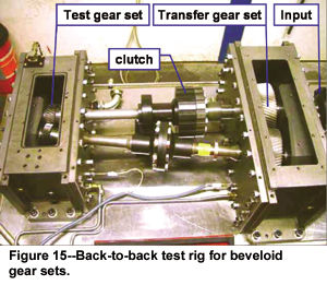
The significant center distance difference guarantees that the transmitting gearing is not damaged--not even during overload testing. Compared to the test gearing, the number of teeth of the transmitting gearing has been doubled for the same ratio to be achieved. This test bench is used to determine S/N curves for tooth root and tooth flank capacity.
Summary
For a six-speed automatic transmission with integrated AWD, a beveloid gear set with 8° shaft angle was developed for a skew drive shaft linked to the front axle, as shown in Figure 16.
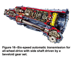
This permitted compact tunnel dimensions. Since mid-2002, the transmission has been in production in a high-end passenger car. Development work included the following tasks:
-Development of specific software for the design and recalculation of beveloids.
-Because of topological corrections, the capacity and noise levels reached are comparable with
those of helical gears.
-Beveloids are cut on NC hobbing machines, and after hardening, they are finish-machined on continuous worm grinding machines.
-Beveloids require comprehensive quality specifications (toe, center, root). Measurements are
carried out on the usual measuring machines, with specific setting values being considered.
-A back-to-back test bench with suitable shaft angle was set up for basic testing. Allowable
stresses have to be determined under different conditions.
This article was previously published by the ASME as part of the 2003 Design Engineering
Technical Conference and Computers and Information in Engineering Conference in Chicago, IL, September 2-6, 2003. It is reprinted with the permission of the ASME.
References
1. Bürkle, R., S. Gandbhir, and F.J. Joachim. "Kegelige Stirnräder zur Leistungübertragung in
Getrieben," ("Conical Gears for Power Transmission in Gear Units.") VDI Report #1056, 1993,
pp. 95-110.
2. Somschor, B., R. Bürkle, S. Gandbhir and H. Schulz. "Conical Gears in Planetary Gear
Transmission for Industrial Robots," VDI Report #1230, 1996, pp. 473-489.
3. Bürkle, R., F.J. Joachim and B. Somschor. "Kegelige Stirnräder in ZF Getrieben," ("Conical
Gears in ZF Gear Units,") Leichtbaukonstruktion und Maschinenelemente, 2. Workshop Konstruktionstechnik, Rostock, 1998.
4. Henning, G.and G. Magnusson. "Sechsgang- Automatikgetriebe und Allradantrieb," ("Automatic
Transmissions and All-Wheel Drive,") Special edition ATZ+MTZ, pp. 60-66.
5. Wagner, M. "Beitrag zur geometrischen Auslegung von Stirnradpaaren mit kleinen
Achsenkreuzungswinkeln," ("Contribution to Geometrical Design of Gear Sets with Small Axis
Cross Angle,") Ph.D. thesis, University Stuttgart, 1993.
6. Roth, K. "Zahnradtechnik-Evolventen-Sonderverzahnungen," ("Gear Technology, Special Involute Gearing,") Springer, 1998.
7. PERMAS - User’s Reference Manual. INTES Publication #450, Rev. F, Stuttgart, 2000.
8. "LVR-Beanspruchungsverteilung an evolventischen Ver zahnungen," ("LVR Distribution of Load and Stress at Involute Gear Sets,") PC program, TU Dresden, 2002.
Dr.-Ing. Jörg Börner works in the corporate research and development department of ZF Friedrichshafen AG and is responsible for basic gear design and development. His responsibilities include developing computer programs for gear design, manufacturing and basic investigations of gears. He joined ZF in 2001, after working at Caterpillar.
Dipl.-Ing. Klemens Humm is in charge of gear design and development of special drives at ZF Friedrichshafen AG. He has been with ZF for the past seven years, having previously programmed gear software for a German gear manufacturer.
Dr.-Ing. Franz J. Joachim is senior manager responsible for the gear development departments in corporate research and development at ZF Friedrichschafen. After studying with the Gear Research Institute, Joachim started with ZF, where he’s worked for the past 20 years. In addition, Joachim is an active member of the National
Standardization Committee and vice president of the Scientific Council of the FVA.


 (1)
(1) (2)
(2) (3)
(3)

 (4)
(4) (5)
(5) (6)
(6) (7)
(7) (8)
(8) (9)
(9)


 (10)
(10)


