It is known that, as a rule, a roller test does not fully represent an exact analogy to a real gear flank. Therefore, typically higher Hertzian stresses can be applied to rollers as opposed to gear flanks, due to geometrical effects. Nevertheless, the relationship between a roller, e.g., one for material testing, can be extrapolated from roller tests to real gears. Therefore a reference within the roller tests is needed (Refs. 9–10).
External Zone of the Rollers Before Testing
Within the examinations described in this report, and in addition to a non-damaged reference, three test rollers are used with different degrees of thermal damage. The thermal damage is realized using a laser. In order to eliminate the influence of the oxide layer after laser damaging, a very small amount of stock has been removed from the roller surface by grinding. The surface of the thermally damaged samples, after the laser process, grinding and nital etching, can be seen in Figure 3.
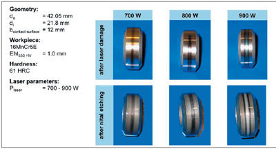
Figure 3—Test rollers.
Four different variants are to be examined:
1. Undamaged (reference)
2. Slightly tempered zone (PLaser = 700 W)
3. Strong-tempered zone (PLaser = 800 W)
4. Rehardening (PLaser = 900 W)
An important factor in the analysis of the laser-damaged rollers is to make sure that the induced damage is comparable to typical grinding burn seen in the gear profile grinding process. In order to analyze the characteristics of the damage, the material structure (Fig. 4), the hardness profile (Fig. 5) and the residual stress profile (Fig. 6) have been analyzed.
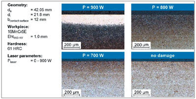
Figure 4—Material structure of damaged test rollers.
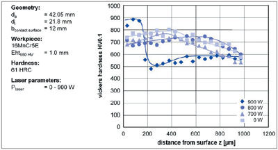
Figure 5—Microhardness profile of selected test rollers.
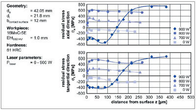
Figure 6—Residual stress profile of selected rollers.
The analysis shows that the occurrence of the thermal damage reveals a good correlation to what would typically be observed on a damaged gear flank; the structural damage goes well below the surface. The tempered samples have a decrease in hardness close to the surface as well as residual tensile stresses. The rehardened sample shows a very high hardness close to the surface layer, with the hardness decreasing inside the tempered zone below the rehardened area. Very high-compressive stresses are also in evidence near the surface, changing into very high tensile stresses at a distance from the surface of z = 200 µm.
It can thus be concluded that the thermal damage caused using a laser shows a very useful correlation to a thermally damaged gear. As such, an acceptable correlation between the load carrying capacity from the roller tests and real gears can be expected.
Test Rig Trials Using Thermally Damaged Rollers
To determine the load-carrying capacity of the thermally damaged rollers, test rig trials have been conducted. The objective was to determine the sustainable load cycles of damaged rollers under high loading when compared to an undamaged reference. The focus was on the sustainable load cycles as well as on the occurring failure mechanisms.
Running time of rollers depending on the degree of thermal damage. To determine the load-carrying capacity of thermally damaged rollers, damaged and undamaged rollers were tested on a twin-disc test rig. The cylindrical test roller on the test rig was in contact with the crowned contra roller. The normal force between the rollers was Fn = 8,708 N, resulting in a Hertzian stress of σHertz = 2,800 N/mm2. The injected oil was a typical lubricant for gearbox applications—Shell Spirax 80 W—at a temperature of ϑÖl = 55°C with a tolerance of Δϑ = ± 3°C. The test roller is rotated at a speed of n = 2,850 min–1, and the sliding between the two rollers amounted to s = –24%.
To determine the fatigue life of the different rollers, the maximum load cycles—depending on the degree of thermal damage—are shown in Figure 7. After reaching N = 50,000,000 load cycles, the limit for the fatigue strength would be reached. Testing was carried out in the area of fatigue life; in this way a comparison of the differing, thermally damaged rollers could be accomplished.
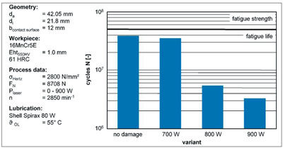
Figure 7—Fatigue life impacted by thermal damage.
The undamaged reference had an average sustainable number of load cycles, until pitting occurs, of N = 38.8 x 10^6, and was therefore near the limit for fatigue strength. The failure mechanism was a pitting on the sliding surface. The rollers with a slight tempering (PLaser = 700 W) failed after an average of N = 35.1⋅106 load cycles. These results demonstrate that a slight tempering results in only a small reduction of sustainable load cycles.
However, the two variants with a more extreme structural thermal damage showed a drastic reduction of fatigue life.
The rollers damaged with a laser power of PLaser = 800 W with a strong tempering failed after an average of N = 5.4 x 10^6 load cycles. This is a reduction of fatigue life of more than 80% compared to the undamaged reference. Also, the failure mechanism changed in that pitting occurred not only on the test roller but also on the contra roller.
The rollers damaged with a laser power of PLaser = 900 W with rehardening failed after an average fatigue life of only N = 3.3 x 10^6 load cycles. The failure mechanism changed again compared to the undamaged reference. The pitting on the test roller did not occur in the middle of the sliding surface but on its side. In this area the thermal damage changes from rehardening to tempered zone.
Analysis of the wear mechanisms. The wear phenomenon to be found on the test rollers after damage occurs is displayed in Figure 8. The non-damaged roller and the two rollers with tempering (PLaser = 700 W and 800 W) show pitting in the middle of the contact area, while the rehardened roller shows pitting on the edge of the contact area.
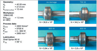
Figure 8—Comparison of pitting depending on degree of thermal damage.
An explanation for the migration of the pitting out of the middle is supplied when Figure 9 is taken into account. The material structure in the area of the pitting is shown. The middle of the contact surface is marked where the hardness profile was measured. The hardness profile shows a high hardness near the surface and a low hardness (tempered zone) below the surface. The pitting occurs on the side of the contact surface.
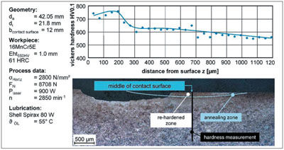
Figure 9—Analysis of pitting on roller with rehardened zone.
The line showing the start of the annealing zone below the rehardening shows that the middle of the pitting is in the area of the changeover from the rehardening to the tempered zone on the surface. This shows that the rehardened area breaks off the tempered zone below, due to the high tensile stresses in this area (Fig. 6).
In Figure 10, pictures of the pitting of all four variants are shown via electron microscope. The undamaged and the slightly damaged variants show pitting with no surrounding cracks. The strongly tempered roller (PLaser = 800 W) shows a crack around the pitting. In this area, the pitting would have enlarged had more load cycles been run. On the other hand, below the pitting on the roller with a rehardened zone, cracks transverse to the sliding direction are found. This documents that the surface is strongly affected and indeed shattered, due to the high hardness of the rehardened area leading to a very low ductility of the material.
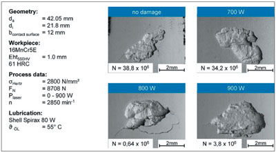
Figure 10—Comparison of pitting using scanning electron microscope.
To gain a more detailed analysis of the surface wear mechanisms occurring on a rehardened roller, the surface has been examined with a scanning electron microscope after a very short time frame of N = 200,000 load cycles; the photos are shown in Figure 11. The upper photograph shows an overview of the sliding surface, and the three lower photographs display a more-detailed image of the middle, left and right areas. In the middle, the ground surface structure remains visible. This is the rehardened area that shows a high resistance to abrasive wear. On the sides, where the tempered material can be found, this structure is no longer visible. The typical grinding structure has been leveled, showing that in this area—even though the Hertzian stress is lower—higher wear occurs.
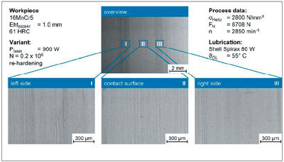
Figure 11—Surface structure of roller with rehardened zone after 200,000 load cycles.
From these results it is concluded that the rehardened area is not the critical factor concerning the fatigue life and the load-carrying capacity of ground parts. Rather, the tempered zone—and especially the area of the changeover between rehardening and tempering—are critical. This demonstrates that rehardening-related grinding burn is very critical since there is always a large, tempered area making the fatigue life of the part unpredictable.
In order to determine the degree of influence of the damage and attendant wear on the sliding surface, the topography of the test roller sliding surface in the axial direction has been analyzed. The undamaged rollers have been analyzed after reaching half the sustainable load cycles (N = 15.4 x 10^6) and at the full sustainable load cycles (N = 38.7 x 10^6). The rehardened roller (PLaser = 900 W) and the strong-tempered roller (PLaser = 800 W) were analyzed after the full sustainable load cycles. The profiles are shown in Figure 12.
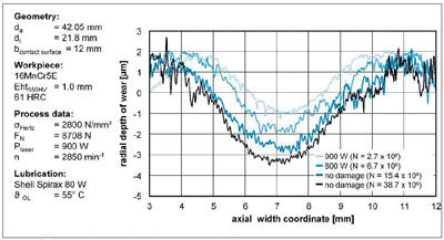
Figure 12—Topography of the test roller contact surface.
Results show that in the middle of the sliding surface there is a change in geometry of up to 5 µm. It can also be demonstrated in Figure 12 that the geometrical change does not depend on the degree of damage, but mainly on the number of load cycles. Only the rehardened roller shows a change on the side of the sliding surface similar to the results shown in Figure 11. Also it must be stated that the crowned shape of the contra roller and the geometrical change of the test roller lead to an increasing contact width, resulting in a reduced Hertzian stress with an increasing number of load cycles.
Summary and Outlook
When using gear grinding processes in a production environment, thermal damages to the external zone—such as grinding burn—can occur. Even with maximum care in process design, grinding burn cannot be fully eliminated. As the round-robin test on nital etching has shown, in the gear industry grinding burn can be reliably detected using a nital etching procedure. The evaluation of the etching result—and the maximum amount of grinding burn that can still be accepted—differ from company to company. This shows that there is a high uncertainty regarding the influence of grinding burn on the load-carrying capacity of gears.
Within the investigations described in this paper, test rig trials were carried out in order to determine the load-carrying capacity of thermally damaged parts under rolling stress. The contact conditions between two gear tooth flanks were simulated using rollers in order to deliver a constant load over the lifetime, and a constant thermal damage in the area under maximum load.
The results show that slight thermal damage to a small tempered zone, and significant tensile stresses, result in only a relatively small reduction in fatigue life. In contrast, more severe thermal damage with a larger tempered zone and a significant decrease in hardness lead to a dramatic reduction in fatigue life. If the part shows a rehardened zone, the fatigue life decreases even further.
From the results it can be concluded that grinding burn always leads to a reduction of fatigue life of parts under generating load. Furthermore, the analysis shows that slight thermal damage has a rather small influence, while significant damage causes a dramatic decrease in fatigue life. Also, it remains very problematic in determining the true level of thermal damage that can be tolerated by using only non-destructive analysis methods.
References
1. Klocke, F. and C. Gorgels. “Ansätze zur Entwicklung eines Schleifbrandkennwertes für das Zahnflankenprofilschleifen,” Tagungsband zur 46, Arbeitstagung, Zahnrad und Getriebeuntersuchungen, WZL, RWTH Aachen 2005.
2. Klocke, F. and C. Gorgels. “Influence of the Process on the Material Properties in Gear Profile Grinding and its Detection Using Barkhausen Noise Analysis,” 5th International Conference on Barkhausen Noise and Micromagnetic Testing, Petten, the Netherlands, 2005.
3. Klocke, F., H. Schlattmeier and C. Gorgels. “Fundamental Investigations in Gear Profile Grinding,” Production Engineering, Vol. XII/2 (2005).
4. Schlattmeier, H. “Diskontinuierliches Zahnflankenprofilschleifen mit Kor-und,” Dissertation RWTH Aachen, 2003.
5. Klocke, F. and H. Schlattmeier. “Zahnfußschleifen einsatzgehärteter Zylinderräder—Tragfähigkeit und Prozessstrategie,” Tagungsband zur 43. Arbeitstagung, Zahnrad und Getriebeuntersuchungen, WZL, RWTH Aachen 2002.
6. Klocke, F. and H. Schlatt-meier. “Entstehung von Randzonenschäd-igungen beim Profilschleifen und deren Auswirkungen auf die Zahnflankentragfähigkeit,” Tagungsband zur 41, Arbeitstagung, Zahnrad und Getriebeuntersuchungen, WZL, RWTH Aachen 2000.
7. Klocke, F. and H. Schlattmeier. “Surface Damage Caused by Gear Profile Grinding and its Effects on Flank Load-Carrying Capacity,” Gear Technology, September/October, 2004, pp. 44–53.
8. Gohritz, A. “Ermittlung der Zahnflankentragfähigkeit mittlerer und großer Getriebe durch Analogieversuche,” Dissertation, RWTH Aachen, 1982.
9. Kotthoff, G. “Neue Verfahren zur Tragfähigkeitssteigerung von ges-interten Zahnrädern,” Dissertation RWTH Aachen, 2003.
10. Hurasky- Schönwerth, O. “Einsatz-verhalten von PVD Beschichtungen und Biologisch Schnell Abbaubaren Synthetischen Estern im Tribologischen System des Zahnkontaktes,” Dissertation RWTH Aachen, 2004.
11. Klocke, F., H. Schlattmeier and C. Gorgels. “Optimization of the Gear Profile Grinding Process Utilizing an Analogy Process,” International Conference on Gears, Garching, Sept. 14-16, 2005, VDI Verlag Düsseldorf, 2005.
Dipl.-Ing. Christof Gorgels is a research engineer at the WZL Laboratory for Machine Tools and Production Engineering. His area of expertise is gear manufacturing, gear hard finishing and especially gear grinding and grinding burn.
Prof. Dr.–Ing. Fritz Klocke is head of the Chair of Manufacturing Technology and a member of the directory board of the Laboratory for Machine Tools and Production Engineering (WZL), a department of the Aachen University of Technology in Germany. Also, he is head of the Fraunhofer Institute for Production Technology in Aachen, Germany.
Dipl.-Ing. Tobias Schröder is chief engineer of WZL’s gear department, where he supervises current projects and proposes future ones. Schröder has conducted several research projects in gear shaving. Also, he completed his doctoral dissertation on gear shaving.


