Scientists are trained to question everything, but what happens if a scientist proves a standard engineering practice to be wrong? Or to be more precise, when science finds a solution where engineering has none, but thinks it has one as the machines that produce gears seem to implicitly solve the problem for them. This despite the fact that spur gears are well know to be noisy and that this should be a warning sign that all is not well.
The short answer is that the engineers ignore it, even when the proof is easy to understand and validate. I will leave to you to consider the deeper meaning of this and instead just present you with the proof. The proof is easy to understand and no previous gearing knowledge is required.
Gears have been around for a very long time and they are used extensively in mechanics. Virtually all gears in use today are of the involute gear type. These involute gears have many advantages that I won’t go into here. But it is safe to say the engineers have put a lot of work into to getting it just right. Involute gearing is seen as a difficult dark art in engineering and few claim to really understand it. Instead engineers use many well-established formulas to calculate their gears (or most often just buy them ready-made).
In involute gearing everything is based on the so called “pitch circle”. This is the imaginary circle with which a gear rolls over the pitch circle of the other gear that it is intermeshing with. This seems like a reasonable starting point when designing a gear system. But from a mathematical point of view this starting point makes no sense.
Mathematically speaking the pitch circle is only something that is derived from the underlying structure, and it is this underlying structure that everything should really be based on. Involute gears use involute curves for the shape of their teeth and in gears all these involute curves start on the so called “base circle”. This base circle then, is what mathematically speaking all the formulas on involute gearing should be based on.
But before we deduct the formula, we can go even deeper.
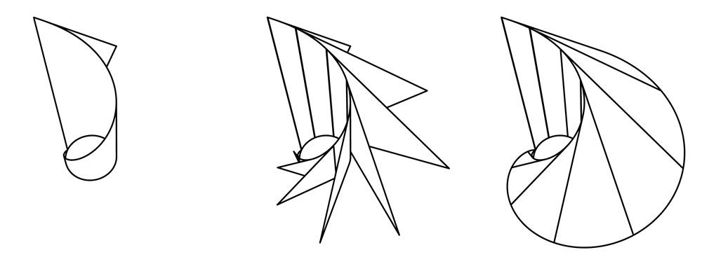
The involute curve itself is often portrayed as a mathematical nightmare, but it too can be deeper analysed to reveal the very simple three-dimensional shape that it is actually based on. This shape is called the “3D involute shape”, and it can be generated by a straight line rotating around, and moving up, a cylinder at a constant rate. So let’s quickly explain this in detail before we go on.
In the graph below we see twelve figures (for a video explaining more see: http://new-cvt.com). Starting with a simple triangle in the top left, and ending with an example of the so called “conical involute gear type” in the bottom right. Horizontal cross-sections of this conical involute gear type are the bases of all the two-dimensional outlines that form the bases of all the other involute gear types. Understanding this is the key to understanding a lot about involute gearing and involute intermeshing. The graph with twelve figures is self-explanatory, but note that figures six and seven show the 3D involute shape. And also note that any horizontal cross-section of this 3D involute shape shows the same involute curve, and that only the starting point of this involute curve on the cylinder changes.
So as you can see the involute curve always starts at some point on the cylinder at the centre of the 3D involute shape. And in two dimensions it is the horizontal cross-section of this cylinder that we call the “base circle”. This explains why mathematically speaking it makes so much more sense to base everything on the base circle rather than on the pitch circle. The pitch circle is depended on the pressure angle, which itself is depended on the vertical height of the cross-section through the basic conical involute gear.
Now let’s get back to deducting the formula.
When calculating the exact shape of involute gears we need to know the exact position where each involute curve starts on the base circle.
A little research on the internet quickly reveals that there many different and mutually exclusive ways in use for calculating this position. All the authors are satisfied that their solution is good enough for what they need. Unfortunately I could not find any clear explanations as to why these solutions would be theoretically valid. It seems everybody is assuming that someone else has the answer and that engineering textbooks simply did not find this knowledge interesting enough to publish. However, true science wants to understand everything, so let’s go for theoretical perfection. It’s also a lot simpler.
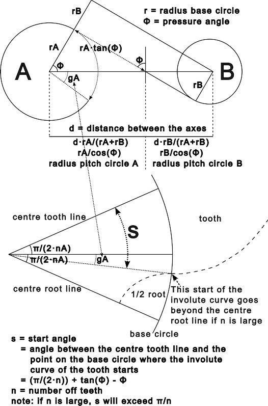
When two gears intermesh with each other there is a point where the contact point between the teeth is exactly on the line between the axes of the two gears, the halfway point so to say. This is known as the “pitch point”. The top figure in the graph below shows a general representation of such a pitch point. This pitch point is very useful as it makes the maths a lot easier as it appears to be a situation of perfect symmetry.
However, if you look closely, you will notice that there is a problem with this perfect symmetry. In order to reach this point, the gear actually had to rotate further than the centre line. This is due to the fact that the involute curve sweeps back as it moves further away from the base circle. And this causes problems. Basically the position of the point of contact on the gear rotates slower than the gear itself. This problem needs to be corrected for in order to make sure that the next tooth comes in at exactly the right time. Otherwise the resulting gearing solution will generate noise and be less efficient. And although the way in which gears are made actually avoids (and hides) a lot of the theoretical problems discussed in the article, the forces acting on the gears are commonly very big so even a small error can cause a lot of mischief. Anybody involved in designing gearing solutions should be aware of this problem.
The problem can be solved by slightly giving the holes between the teeth, generally known as the roots, less space on the base circle. The result is theoretically perfect gearing and practically speaking the gearing is smother, quieter, more efficient and the production costs remain the same, so it just works better.
The formula I am about to deduct relates to all involute gearing. I found it when I was developing the New-CVT (see: http://new-cvt.com) as I modelled it in 3D software and I could really zoom in deep. I wrote the formula that solves this problem into the patent, so patent is pending. The source code is available on the website for those wishing to test the formula. By the way, in the graphs the scale factor is way out in order to have enough space to put in all the texts. So please ignore that. Also the gearing nomenclature was not always followed in order to achieve better mathematical clarity.
The top graph shows the situation where the point of contact between the two intermeshing gears is exactly on the line between the centres of the two gears (the pitch point). Gear “A” has a base circle radius of “rA” and both gears have a pressure angle of “Φ”. This results in the distance between the centre of gear “A” and the pitch point being “rA/cos(Φ)”. This distance is also known as the radius of the pitch circle of gear “A”.
Above this horizontal line is a part of a tangent line between the two gears (dotted straight line with arrows). The length of this line between gear “A” and the pitch-point is “rA·tan(Φ)”. Now a fundamental property of the involute curve is that this length is equal to the length of the circumference covered on the base circle of gear “A” (dotted arc line with arrows). So both dotted lines are of exactly the same length. From this we can then calculate the angle that gear “A” rotated in order to reach the pitch-point and this angle is “tan(Φ)”. Now as you can see from the graph, the point of contact between the intermeshing gears rotated over exactly “Φ” in order to reach the pitch-point. So the difference between these two rotations is “gA” and this angle is the extra amount of rotation that we need to compensate for.
With this we can now deduce the formula. Starting from the centre line of the tooth, the angle (all angles in rad) that we need to rotate over to reach the point where the involute curve of the tooth starts on the base circle is: “(π/(2·n)) + tan(Φ) - Φ”, whereby “n” is the number of teeth of the gear and “Φ” is the pressure angle. In the graph “s” is used to indicate this start angle.
Now you might notice that if n becomes large that s becomes larger than the space available for half a tooth on the gear. This is correct. The involute curve is simply cut at the centre root line. Theoretically speaking the involute curve still starts at the base circle, it is just that the starting point on the base circle is out of range when n is large.
The start angle that we have deduced here can also be used as a starting point for changing the thickness of the teeth of the two intermeshing gears, and without changing the distance between the axes of the two gears. If we have two intermeshing gears A and B, with teeth numbers nA and nB, with starting angles sA and sB and we define an offset of f. Then: sAnew = sAold + f/nA and with sBnew = sBold - f/nB. By using this relationship we can make the teeth of one gear thicker by making the teeth of the other gear thinner. The simplicity of this relationship very much supporting the notion that it is the base circle that is the truly important underlying structure in involute gearing.
One final note. There are well-established formulas for where to cut the tips of the teeth and how deep the roots need to be. However I found it best to just model and optimise these in the software. Standard practice is great for general solutions and it works well in most cases, but improvements are generally possible. Be a scientist and go for theoretical perfection, deeper insight will show you options you would otherwise never consider. And my apologies for this slightly cheeky article, but engineers should have found this knowledge literally centuries ago. Always relying on historical precedence and the immediate need for practical solutions can blind you. Do not assume that what you were taught is always correct. Scientists are always on the lookout for implicit assumptions in the generally accepted knowledge that are false, this is the true hart of science. All I did was to look at involute gearing with a scientific mindset. I am not a genius, just a scientist that got lost.