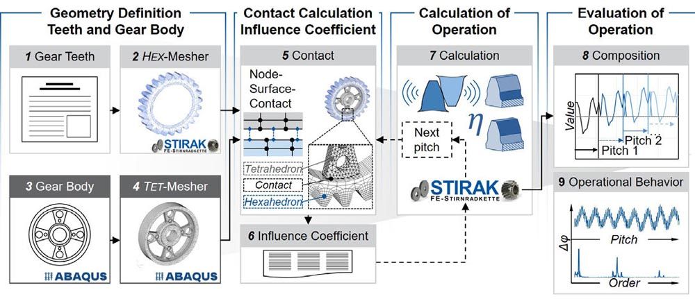
The contact between the gear body and the gear rim is made via the extended node-surface contact with the SolverZ88 (step 5). In this process, the surface is additionally discretized with the Gaussian support points so that the location of the smallest distance can be determined as precisely as possible during the contact search (Ref. 16). If the distance is smaller than a numerical tolerance, a contact constraint is defined for the current contact pair and incorporated into the equation system of the finite element analysis using the perturbed Lagrangian method (Ref. 17). In this application, a bonded contact (i.e., a transmission of both normal and tangential forces) is required. With the bonded FE model of the gear, the influence coefficient are calculated in the sixth step (step 6), analogous to the general procedure of FE-based tooth contact analyses (Ref. 13). The load definition is taken from the FE-based tooth contact analysis and the gear body is bound in the bore. Then, the system of equations is solved with the SolverZ88 and the FE-based tooth contact analysis is used to calculate the operational behavior (step 7). The operational behavior includes the characteristic values such as the transmission error, tooth flank pressure, tooth root stress and efficiency. The gear body modifications lead to a circumferential stiffness variation in the tooth contact. Therefore, it is necessary to calculate and evaluate the gear body influence over one revolution of the modified gear. For evaluation, the calculation results are combined (step 8). In this way, the long-wave effects on the operational behavior can be evaluated. The result of the method is the characteristic values of the operational behavior over the revolution of the gear body–modified gear (step 9).
Calculation of the Vibration Behavior
The vibration behavior is calculated in Abaqus CAE, see Figure 2. A modal analysis is performed in the loaded tooth contact. The objective is to evaluate the influence of the gear body density and geometry on the transfer function of the gear. The vibration behavior is analyzed under operating conditions, taking into account the support effects in the tooth contact. Analogous to the calculation of the operational behavior, the geometry of the gear rim and teeth (step 1) is meshed with a parameterized FE hexahedral mesh from the tooth contact analysis (step 2). The gear body geometry is automatically created and parameterized in Abaqus CAE and freely meshed with a FE tetrahedral mesh (step 3). The contact between the gear body and the gear rim is made via the node-to-surface tie constraint, where the main surface is assigned to the gear rim and the secondary surface to the gear body (step 4). The tooth contact is defined by the surface-to-surface contact with finite sliding (step 5). The surface-to-surface contact definition offers more precise stress and pressure results if the contact surface geometry is sufficiently accurate (Ref. 4). To reduce the contact search effort, only the tooth flank surfaces are defined as contact pairs.
For the general component definition, the geometry, the material density and the resulting material stiffness and material damping are specified. This is followed by the alignment of the two gears according to the center distance in the same coordinate system. Rotationally, the gear teeth are aligned with each other in such a way that there is an initial penetration of the tooth flank surfaces of one percent of the pitch of the gear. For connection to the environment, the bore of each gear is connected in the center of the axis to an axis reference node by a structural coupling (step 6). Along the two axes, two further environment reference nodes are defined, which are connected to the axis reference nodes by spring elements. The environment reference nodes are bounded in all spatial directions. With the specification of the spring stiffnesses in axial, radial and rotational direction, the connection of the gear teeth to the surrounding system is defined.
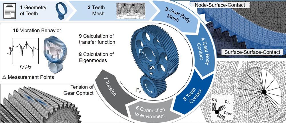
Figure 2—Method for calculating of the vibration behavior.
The first calculation step is the preload of the gears (step 7). Torque is applied at the axis reference node of the pinion. In the Static calculation step, the torque is increased successively in 10 steps until the final torque is reached. The successive increase of the torque is chosen to ensure a stable solution of the calculation. In accordance with the defined spring stiffnesses, the gears turn until the force equilibrium between the spring force and the applied torque is achieved in each time step. At the end of the calculation step, the tooth contact is statically tensioned. The second calculation step Frequency is the determination and visualization of the natural frequencies of the system (step 8). The natural frequencies of the gear set are determined for a defined frequency range, taking the tooth contact into account. The result contains the frequencies and shapes of the eigenmodes. The determination of the frequency-based vibration behavior is performed in the third calculation step Steady-State-Modal under forced force excitation (step 9). For excitation, a periodic torque excitation is defined at the axis reference point of the pinion. The load is applied with a force amplitude of FA = 1 N along the path of contact. To evaluate the transfer function, the frequency is successively increased. The vibration behavior is evaluated by analyzing the eigenmodes and the resulting structure-borne noise emission at the inner diameter and outer diameter of the gear body on the line connecting the two axis reference points (step 10).
Mechanisms of the Gear Body to Optimize the Noise Behavior
The noise behavior of technical systems is influenced by several mechanisms. The two basic mechanisms are structure-borne noise damping and structure-borne noise insulation. The challenge is to transfer the mechanisms to gears and to systematically design and investigate them separately. In the case of PM gears, both the density and the gear body geometry can be used to optimize the noise behavior. Figure 3 shows mechanisms of the gear body to optimize the noise behavior.
Reducing material density leads to an increase in material damping (Ref. 2). As a result, more vibration energy is dissipated to the environment. The reduction in material density is limited by material load carrying capacity. While the highly loaded teeth are densified as much as possible, the material density of the gear body can be reduced. In addition to material damping, a density reduction in the gear body also causes a material change due to the density-dependent stiffness. According to the Snellius refraction law, the structure-borne noise transfer is influenced with respect to the energy content of the wave types due to different elasticity moduli (Ref. 3). Accordingly, the reduction of the gear body density can be attributed to the mechanism of both material damping and insulation.
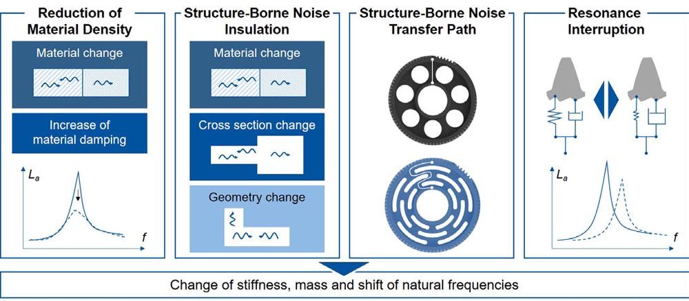
Figure 3—Mechanisms of the gear body to optimize the noise behavior.
In addition to material changes, structure-borne noise insulation can be achieved by geometric modifications. Gear body modifications increase the number of impedance elements. Impedance elements, such as material changes or cross-section changes, lead to reflection and transmission of the individual wave types, which changes the energy distribution between the wave types (Ref. 3). The change in geometry affects the stiffness and mass, causing the number and location of natural frequencies to differ from the unmodified gear (Ref. 2). Due to this, a different frequency-dependent vibration behavior is expected.
The structure-borne noise transfer path is another mechanism resulting from gear body modifications. Due to cut-outs, the direct path between the gear body outer diameter and inner diameter is interrupted. So the structure-borne noise transfer taking place via the remaining material sections. In the case of excitation above a cut-out, the structure-borne sound transfer path is extended, resulting in an optimization of the noise emission according to Dietz et al. (Ref. 5).
With gear body modifications, the stiffness of the wheel body and the mesh stiffness in the tooth mesh change, resulting in a stiffness modulation over the circumference (Ref. 18). The resonant frequencies of the system are directly related to the stiffness. Accordingly, a varying stiffness in the tooth contact leads to a varying resonant frequency over the revolution of the gear. The excitation frequency of the tooth contact can therefore no longer be equal to the resonance frequency, which dampens the resonance of the system. This mechanism is described below as resonance interruption.
The mechanisms make it possible to optimize the noise behavior. For a systematic investigation of the mechanisms, test gear variants are designed and characterized below. The challenge is the separation of the individual mechanisms, whereby the greatest potential for optimization is assumed to lie in a combination of the two basic mechanisms of structure-borne noise insulation and damping.
Test Gears
The design of the test gears is based on the first gear stage of an electrical car transmission. While the gear macrogeometry is based on an industrial application, the microgeometry is designed for high robustness against manufacturing and assembly deviations. The cylindrical gear has a normal module of mn = 1.42 mm, a number of teeth zgear = 81, a normal pressure angle αn = 19° and a helix angle β = 19°, see Figure 4. The gear body is designed as a web with a web width of bweb = 12 mm. The gear body modifications are designed and manufactured within this web. The gear width is bGear = 29 mm.
The pinion is designed with regard to achieve a center distance of a = 91.5 mm. With a number of teeth of the pinion of zpinion = 40, a gear ratio of i = 2.025 results. In contrast to the gear, the pinion has a higher width bpinion = 32 mm to compensate assembly or manufacturing deviations in the axial direction. The microgeometry is also designed regarding assembly and manufacturing deviations. Any potential misalignments during the experimental test rig investigations need to be compensated by the microgeometry so that the resulting influences do not affect the validation of the calculation results.
In addition to an unmodified, rotationally symmetrical reference variant, six different gear body geometries are designed. Notches are designed for three variants. One variant is designed with notches as a labyrinth variant. In two other labyrinth variants, further notches lead to labyrinth structures. With the increasing number of notches in the labyrinth structure, the structure-borne noise transfer path increases as well as the number of impedance elements. In addition to the labyrinth variants, three bore variants are investigated. Gear body bores are often used in the industry because of their low manufacturing cost. The results of the investigation of the three bore variants address the mechanism of resonance interruption. While the comparison of variants B1 and B3 highlights the influence of the bore diameter, the comparison of variants B1 and B2 evaluates the influence of the gear rim thickness on the excitation and vibration behavior.
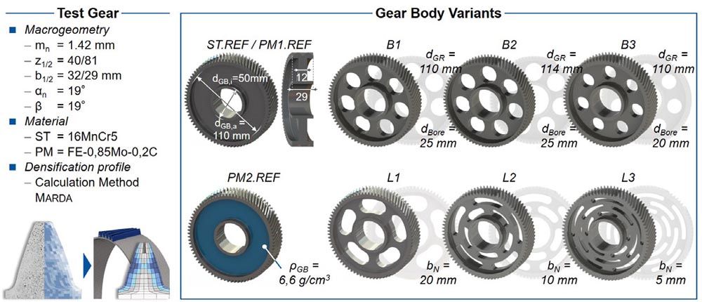
The test gears are manufactured conventionally from the material 16MnCr5 (ST) and powder metallurgically from the material FE-0.85%Mo-0.2%C (PM1/PM2). The PM1 variants, except for the local densification profile of the teeth, has an overall density of ρPM1 = 7.15 g/cm3. For the PM2 variant, the gear body density is reduced by Δρ = 7.7% to ρPM2 = 6.60 g/cm3. The density of the teeth and the hub are equal to the PM1 variants. The densification profile of the teeth is also the same. As a result of the reduced density of the gear body, the PM2 variants have a lower material stiffness and a higher material damping of the gear body (Refs. 2, 7).
Validation of Calculation Methods
The focus of the investigation of the gear body influence is the analysis of the resulting acoustics of the gearing. The acoustics include the excitation and vibration behavior as well as the dynamic noise behavior. The aspects are investigated experimentally with the WZL cylindrical gear measuring cell and the WZL structure-borne noise transfer test rig and compared with the calculation.
Conception of the Experimental Investigation
The experimental investigation of the excitation behavior is carried out with the WZL cylindrical gear measuring cell on the electrical power circle test rig (EVP) in the running test. The design of the measuring cell is described in Klocke et al. (Ref. 13). For the validation of the calculation results, contact pattern, transmission error profiles, order cuts over the torque and order spectra are evaluated and compared. The Marda calculation method is used to adjust the FE-Model regarding the densification profile (Ref. 1). The measured quasistatic transmission error of the experiment and the simulation are compared. The deviation between the measured results and the simulation results provides the measure of validation of the calculation.
In order to measure the misalignments due to assembly, the test procedure was started with a contact pattern test at three torque levels (T2 = 20 Nm, T2 = 100 Nm, T2 = 200 Nm). In the next step, the test rig was warmed up for t = 45 min. The measurements were performed at a constant oil temperature of T = 60°C. After this, the transmission error test was carried out in accordance with VDI 2608 (Ref. 23). At a drive speed of n1 = 60 rpm, the torque was successively increased in 14 steps from T2 = 20 Nm in ΔT2 = 20 Nm steps up to a maximum torque of T2 = 280 Nm and the transmission error profile of the gear sets was measured. In addition to the order spectrum, order cuts are evaluated for the gear body orders and the first gear mesh order.
The influence of the material density and the gear body geometry on the vibration behavior is investigated with the developed WZL structure-borne noise transfer test rig, see Figure 5. Since the gears do not rotate, the gear body positioning is varied. The transfer functions on the inner and outer diameters of the gear body are used to analyze the vibration behavior.
The construction of the structure-borne noise transfer test rig is based on a statically tensioned system in which the meshing conditions of the test gear set under load are reproduced. The base plate for position and assembly forms the basis of the design. To achieve the working height, the base plate is mounted on two pyramids. Both pyramids are filled with quartz sand, which dissipates external and internal vibration energy. The two test gears are mounted on the pinion shaft and gear shaft with an interference fit and are axially secured with a precision shaft nut. The shafts are designed with respect to a low moment of inertia and the natural frequencies outside the frequency range under investigation. The shafts are mounted via pivot bearings. Pivot bearings are solid-state rotational bearings, allowing torsion and torsional vibration of the shafts. The forced excitation of the system is achieved by the force excitation of the pinion shaft with a piezo actuator. According to the radial force support of the pivot bearings, the translational force excitation via the lever results in a rotational excitation of the pinion shaft. The excitation point is positioned in the contact path of the gear mesh, whereby the excitation is tangential to the base diameter of the pinion.
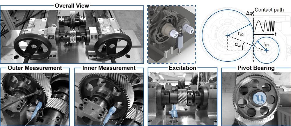
Figure 5—Structure-borne noise transfer test rig.
The structure-borne noise transfer test rig enables an evaluation of the gear material and the gear body geometry with regard to the vibration behavior. As a result of the forced excitation via a piezo actuator, the interaction with the excitation in the tooth contact is not present. Despite this, the excitation takes place via the tooth contact, whereby the force direction components are formed according to the gear geometry.
The final step of the investigation is the transfer of the quasi-static excitation characteristics due to the material density and gear body geometry as well as the vibration behavior to the dynamic noise behavior. For this purpose, the WZL cylindrical gear measuring cell is used for dynamic speed run-ups at constant load levels on the electrical power circle test rig. The structure-borne noise emission is measured at the bearing positions of the measurement cell. In addition to the evaluation of the structure-borne noise emission, psychoacoustic parameters are analyzed, which describe the human hearing characteristics. Loudness and sharpness are evaluated in accordance with the DIN 45631/A1 standard (Ref. 6). The parameters tonality and roughness are based on the hearing model of Sottek, which is integrated in the used evaluation program Artemis-Suite 12.7 (Refs. 19, 20).
Excitation Behavior
The alignment of the gears was qualified with a contact pattern test. As a result of the profile and width crowning as well as the tip relief, there is no flank contact in the tip or root area and no edge contact. Accordingly, no assembly or manufacturing deviations were found which are not compensated by the tooth flank modifications, see Figure 6. As the torque increases, the contact pattern of the tooth flank increases uniformly. An influence of the gear body modifications on the contact pattern is not detected in the investigations. The calculation result also reflects the observations described and shows no significant deviations from the experiment, which validates the calculation method with regard to the contact pattern. The excitation behavior of the test gears is influenced by two mechanisms: The lower stiffness due to the material density and due to the gear body modifications.
With lower density or lower material stiffness, the transmission error profiles over the torque of the PM variants are shifted towards lower loads compared to the ST.REF variant. This shift of the transmission error profile is defined as load shift. The load shift is load-dependent and increases exponentially with higher load. The effect can be observed for the first as well as for the higher harmonic gear meshing orders and is described by Brecher et al. (Ref. 1).
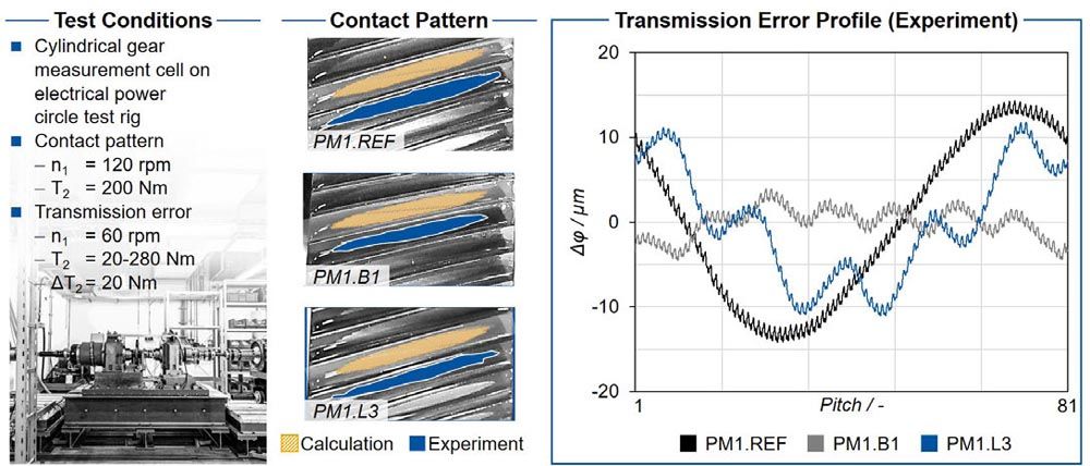
Figure 6—Test conditions, contact pattern and transmission error profile.
The influence of the gear body on the transmission error is shown in the diagram on the right. The reference variant shows a long-wave transmission error component of the first rotational order as well as the short-wave transmission error component resulting from the tooth contact. The long-wave component arises as a result of long-wave deviations of the drive train components as well as the gearing, which lead to an eccentricity or runout deviation. Without these deviations, only the short-wave component would be present. The variation in stiffness due to the gear body modifications superimposes the first rotational order transmission error component with the gear body order. In the case of the bore variants, as a result of the seven bores in the gear body, seven additional local maxima and minima are recorded in the longwave transmission error per revolution. In the labyrinth variants, the five notches are reflected in five maxima and minima in the long-wave transmission error. The modulation of the transmission error profiles results from the stiffness variation in the tooth contact and confirms the result of the calculation method.
Figure 7 shows the order spectrum on the left side. The order spectrum shows the significant amplitude of the gear body and gear mesh orders. On the right side, the order cuts of the first gear mesh order and the gear body order over torque are shown. The amplitude of the first gear mesh order over the torque first drops to a minimum and then rises again. The minimum results from the change in the load-induced overlap. With increasing load, the transmission error amplitude increases again and, after reaching the local maximum, decreases towards the end of the investigated torque range. The calculated profiles as well as the amplitude of the transmission error of the first tooth meshing order match with the experimental measurement results, which validates the calculation method for the first tooth mesh orders.
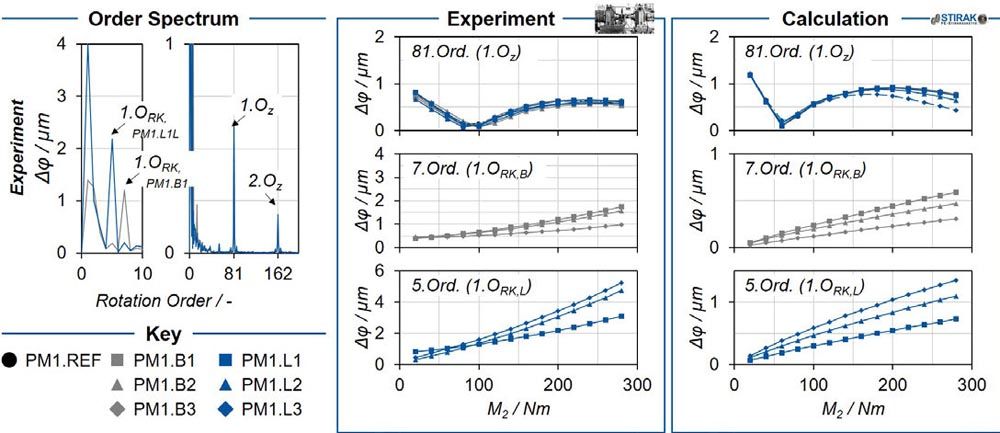
Figure 7—Order cuts of the first gear mesh order and gear body order.
In contrast to the gear mesh orders, the transmission error amplitude of the gear body orders increases linearly with increasing torque. The profiles match between the experiment and the simulation results. The excitation of the gear body order can be assigned to the stiffness modulation over one revolution of the gear. Since the stiffness is proportional dependent to the force, the profiles can be classified as physically plausible. While the amplitudes of the first and second gear mesh order in the experiment and in the calculation show a comparable amplitude, the amplitude of the gear body order is underestimated in the calculation. This deviation is attributed to the influence of the natural frequencies during the transmission error measurement. As a result of the excitation of the natural frequency of the test rig by the gear body frequency, the amplitude of the gear body order increases in the experiment. The calculated amplitudes of the gear body order are lower than the experimental results by a constant factor of about four. However, the gradations between the variants are clearly reproduced and agree with the experiment. The comparison between variants, which is crucial for the design of gearing, can thus be validated.
NVH Behavior
The influence of material density and gear body modifications on vibration behavior and structure-borne noise transfer is investigated using the WZL structure-borne noise transfer test rig. The transfer function between measured acceleration and excitation force is analyzed for evaluation.
Influence of material density on vibration and noise behavior
Figure 8 shows the influence of material density on the vibration and noise behavior in the structure-borne noise transfer test rig and in the running test. To determine the influence of material density, the reference geometry of the two material variants ST.REF and PM2.REF is compared. The comparison addresses the influence of a lower gear mesh stiffness, higher material damping and impedance due to the low gear body density of PM2.REF. The two middle diagrams show the experimental results on the structure-borne noise transfer test rig (top) and the calculation results (bottom). The vector sum of the three spatial directions of the acceleration is analyzed force-normalized at the inner diameter of the gear body.
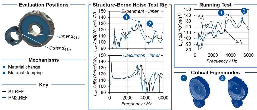
Figure 8—Influence of material density on vibration and noise behavior.
The results show a reduction of the acceleration due to the reduced gear body density. Only in the range around f = 2000 Hz is a higher acceleration measured for the PM variants compared to ST.REF. The PM variant show a lower acceleration at the inner diameter of the gear body, especially in the higher frequency range from f = 3500 Hz. Accordingly, a reduction in structure-borne noise transfer is attributed to the reduced material density. There are a total of six resonance frequencies in the frequency range investigated. Of these, two eigenmodes critical for operation can be identified (fcrit,1 ≈ 3600 Hz, fcrit,2 ≈ 5300 Hz). As a result of the reduction in material density, the resonant frequencies of the gear set decrease.
On the right side of Figure 8, the structure-borne noise emission of the first and second gear mesh orders is shown versus frequency in the running test. While the profile of the structure-borne noise level of the second gear mesh order in the first half of the speed range is comparable to the profile of the first gear mesh order, the maximum amplitude is reduced by about ΔLa = 10 dB. At higher frequencies f > 3000 Hz, the structure-borne noise level of the second tooth meshing order - in particular of the reference variant ST.REF—increases to a maximum of La,ST.Ref = 140 dB.
The two critical resonance frequencies identified in the calculation as well as in the experiment can be transferred to the running test. The reduction in structure-borne noise transfer can also be transferred to the running test. Despite comparable excitation in the gear mesh, the lower material density of the PM variants—especially in the higher frequency range—leads to a reduction in structure-borne noise emission. Due to the low material density, the frequency of the maximum structure-borne noise emission is shifted and a reduced amplitude is measured.
Influence of gear body bores on vibration and noise behavior
The stiffness modulation in the tooth contact of the gear body modified variants leads to a different vibration behavior depending on the gear body position investigated, see Figure 9. The comparison between the measurement result over a bore and over a web addresses the mechanism of resonance interruption. Due to the piezo actuator there is no change of excitation over a PM1.B2 bore and a PM1.B2 web in the WZL structure-borne noise transfer test rig.
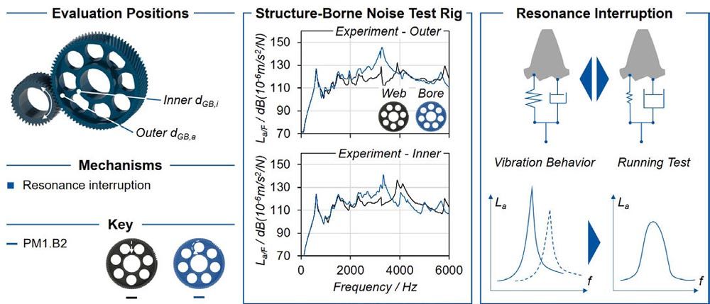
Figure 9—Resonance interruption.
As a result of the lower gear mesh stiffness over the bore, the resistance to vibration insertion is lower. The result is a higher acceleration at the outer diameter of the gear body. There is a significant change in vibration behavior between the two gear body positions. This confirms the mechanism of resonance interruption. At the inner diameter of the gear body, the change in gear body position causes a significant change in the frequency of the maximum acceleration. The higher acceleration at the outer diameter of the gear body is compensated due to the low structure-borne noise transfer over the bore.
With regard to the resonance interruption as a result of the gear body modifications, it should be noted that both the vibration insertion into the system and the structure-borne noise transfer differ depending on the observed position. A shift of the maximum amplitude over the frequency can be observed. Due to the continuous change between the two gear body positions during rotating operation, there is no continuous excitation of the two states. Accordingly, a lowering of the maximum amplitude is expected, which leads to an improved noise behavior due to the gear body modifications. Since the reference variants are measured over a web due to their geometry, the comparison with the gear body modified variants is carried out on the basis of the gear body position over the web.
Figure 10 shows the test results of the variants with bores PM1.B2 and PM1.B3 on the vibration and noise behavior compared with the reference variant PM1.REF out of the same material. As a result of the change in the mass and stiffness of the gear body, the resonance frequencies and the structural damping of the critical eigenmodes are shifted. With respect to the first critical eigenmode around f1,krit ≈ 2300 Hz, the structure-borne noise emission of the bore variants is below the reference variant. At the second critical eigenmode f1,krit ≈ 4100 Hz, a significantly higher structure-borne noise amplitude (over the web) is recorded. The different vibration behavior is also represented in the calculation and can be transferred to the running test.
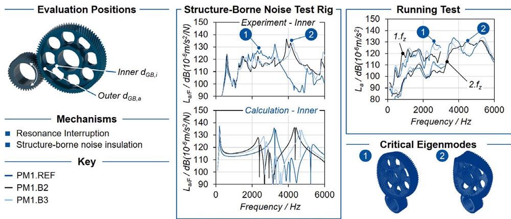
Figure 10—Influence of gear body bores on vibration and noise behavior.
Despite the significant resonances in the structure-borne noise transfer test rig, a reduction of the maximum structure-borne noise emission is recorded in the running test. Here, the mechanism of resonance interruption leads to a reduction of the maximum amplitude, so that this mechanism is confirmed.
A systematic influence of the different labyrinth structures on the structure-borne noise transfer cannot be identified. The thin-walled gear body structure lead to a higher number of natural frequencies in the investigated frequency range. Corresponding to the increased number of natural frequencies compared to the reference, an increased number of local maxima of the structure-borne sound emission occur in the frequency range. Despite the higher structure-borne noise transfer path and the increase in the number of impedance elements in the gear body from the PM1.L1 to the PM1.L3 variant, there is no significant decrease in the body-borne noise emission. Nevertheless, individual frequencies are reduced or damped. Labyrinth structures thus offer the possibility of reducing the vibration behavior only in certain frequency ranges. The advantage of labyrinth structures in the gear body can therefore be used primarily in drive systems with a small number of operating points, whereby the labyrinth structure is designed for this operating point or specific frequency. In drive systems where a wide frequency range is run through, the higher number of natural frequencies is not recommended.
Conclusion
As a result of the mass, the stiffness and the damping mechanisms of the gear body, a different excitation and vibration behavior results. The WZL structure-borne noise transfer test rig is developed to investigate the vibration behavior. In non-rotating operation, a forced excitation with a piezo actuator takes place via the tensioned gear mesh. The reduction of the material density causes a lowering of the maximum structure-borne noise level as well as a reduction of the structure-borne sound transfer at higher frequencies. The mechanism of resonance interruption is confirmed. As a result of the varying stiffness due to gear body modifications over the revolution of the gear, the vibration behavior changes, reducing the maximum structure-borne noise amplitude.
The lengthening of the structure-borne noise transfer path and successively increasing number of impedance elements in the gear body are investigated with labyrinth structures. A systematic influence of the different labyrinth structures on the structure-borne noise transfer cannot be identified. The thin-walled gear body structures lead to an increased number of natural frequencies in the investigated frequency range, which are not compensated as a result of the impedance elements and the structure-borne noise transfer path.
The results of the investigation of the vibration behavior on the WZL structure-borne noise transfer test rig can be transferred to the noise emission in the dynamic running test. While the labyrinth structures show no systematic influence on the noise behavior, an optimization of the noise behavior is achieved as a result of the reduced gear body density and gear body bores. As a result of the resonance interruption, the maximum structure-borne noise level of the gear mesh frequencies is reduced. The low overall material density and additionally lower wheel body density also result in a reduction in structure-borne noise emission of the first and second gear mesh frequencies.
NVH Optimized Gear Body
The PM2.B3 variant combines the two mechanisms of structure-borne noise damping and insulation. The lower gear body density leads to an increase in material damping, while the gear body bores result in impedances and resonance interruption. Figure 11 shows the results of the PM2.B3 variant compared with the conventional ST.REF reference variant. The combination of reduced gear body density and bores leads to a significant reduction in structure-borne noise emission, especially with regard to the second gear mesh order. Both the mean value of the second tooth meshing frequency decreases by ΔLa = -12 dB and the maximum structure-borne noise amplitude decreases by ΔLa = -12.4 dB. As a result of the material damping and the material change, the reduced gear body density causes a reduction in structure-borne noise emission in the higher frequency range from f = 3400 Hz. The gear body bores result in a reduction of the maximum level due to the resonance interruption and an optimization of the low frequency range. The reduced structure-borne noise emission of the PM2.B3 variant compared with the ST.REF variant is attributed to the sum of the mechanisms, whereby an optimization of the noise emission is achieved in the entire frequency range.
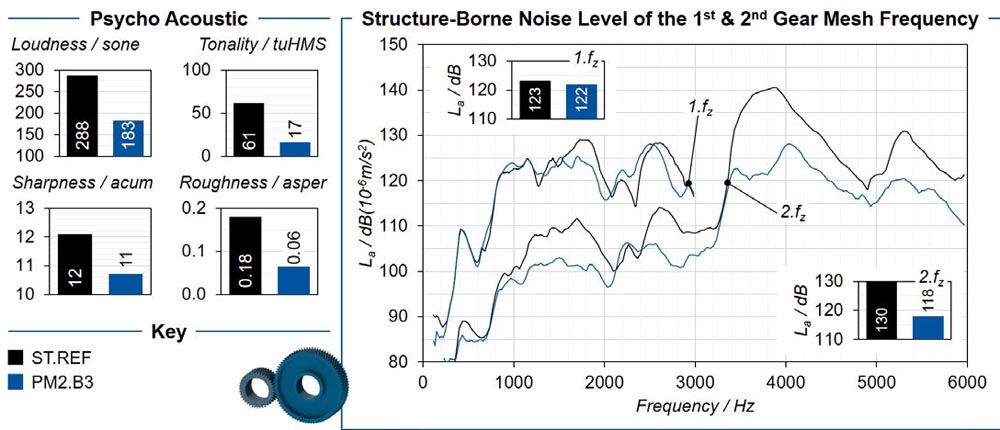
Figure 11—Reduction of NVH behavior through a combination of gear body geometry and density.
The comparison of the psychoacoustic parameters of the two variants also shows a significant optimization of the noise behavior of the PM2.B3 variant compared to the reference. Loudness is reduced by -36.5 percent, tonality by -72.1 percent, sharpness by -7.3 percent and roughness by -66.7 percent. The reduction of the characteristic values is mainly due to the reduction of the structure-borne sound level of the second tooth meshing frequency in the higher frequency range.
Summary and Outlook
The reduction of noise emission is a general objective of transmission design. In addition to the macro- and microgeometry, the design of the gear body geometry and density can optimize the NVH behavior as a result of the mechanisms influencing the vibration behavior. The partly counteracting mechanisms of influence require a multidimensional evaluation of the operational behavior. Therefore, calculation methods of the gear body influence on the operational behavior and on the vibration behavior are developed and validated by the experimental test results. For the systematic investigation of the mechanisms influencing the vibration behavior, nine test gear variants are designed, which differ in terms of material, density as well as gear body geometry. To evaluate the influence of the gear body variation, excitation, vibration and dynamic structure-borne noise behavior are investigated experimentally. Due to the gear body modifications, the gear mesh stiffness varies over the circumference, which results in a discontinuous stiffness characteristic. This leads to an excitation of the gear body order and sidebands besides the gear mesh frequencies. The lower material stiffness of the PM variants causes a load shift of the transmission error profile of the gear mesh orders. As a result, there is a shift in the minimum and maximum excitation regarding load, which is relevant for the design. For the optimization of the NVH behavior, the mechanisms of material damping, material change and resonance interruption show the greatest influence. With regard to an extension of the structure-borne noise transfer path and the number of impedance elements, no systematic influence can be measured. The combination of a reduced gear body density and bores in the gear body of the PM2.B3 variant combines the three most potential mechanisms. The test results show that the influence of the mechanisms superposes, resulting in a significant optimization of the NVH behavior. Both the structure-borne noise level of the first two tooth meshing frequencies and the psychoacoustic parameters are significantly reduced.
Overall, the influence of gear body modifications and material density is multidimensional. The excitation in the gear mesh, the stress, the vibration behavior and the NVH behavior are influenced. The results of the systematic investigation are the basis for a resource-efficient, noise-optimized design of the gear body of powder-metallurgical gears. The future goal is to integrate the gear body design into the gear design, which has so far focused on the gear macro- and microgeometry.
Acknowledgement
The authors gratefully acknowledge financial support by the German Research Foundation (DFG) [BR2905/98-1] and the WZL Gear Research Circle for the achievement of the project results.
References
- Brecher, C.; Löpenhaus, C.; Scholzen, P.: Influence of the densification profile on the excetation behavior of PM gears. Euro PM2017 proceedings 1-5 October 2017, Milano Congressi (MiCo), Milan, Italy. Shrewsbury, United Kingdom, Shrewsbury, United Kingdom: European Powder Metallurgy Association (EPMA), 2017.
- Brecher, C.; Löpenhaus, C.; Scholzen, P.: Analysis of the Damping Potential of Powder Metallurgical Manufactured Gear Bodies. 14-18 October 2018, Bilbao Exhibition Centre (BEC), Bilbao, Spain. Shrewsbury, United Kingdom: European Powder Metallurgy Association (EMPA), 2018.
- Cremer, L.; Heckl, M.; Petersson, B.A.T.: Structure-Borne Sound. Structural Vibrations and Sound Radiation at Audio Frequencies. 3rd edition. Aufl. Berlin, Heidelberg: Springer-Verlag Berlin Heidelberg, 2005.
- Dassault Systèmes: Abaqus Documentation 2021. https://www.3ds.com/products-services/simulia/servicessupport/support/documentation.
- Dietz, P.; Schmidt, A.: Impedanzelement. Entwicklung von Konstruktionsrichtlinien zur gezielten Beeinflussung der Körperschalleitung an Zahnradkörpern mit Hilfe von Analogiebetrachtungen und Modellversuchen im Bereich der dynamischen Spannungsoptik. Abschlussbericht zum FVA Forschungsvorhaben Nr. 235, Heft 522, Forschungsvereinigung Antriebstechnik e.V., Frankfurt a.M., 1997.
- DIN Deutsches Institut für Normung DIN 45631/A1 (03.2010) Berechnung des Lautstärkepegels und der Lautheit aus dem Geräuschspektrum – Verfahren nach E. Zwicker.
- Flodin A.; Brecher, C.; Gorgels, C.; Röthlingshöfer, T.; Henser, J.: Designing Powder Metal Gears. In: Gear Solutions, August 2011. Jg., 2011, S. 26–35.
- Frech, T.; Klocke, F.; Gräser, E.: Potential of PM process chains with profile modified densifying tools International Conference on Gears 2015. München, 5.-6. Oktober 2015. Düsseldorf: VDI-Verl., 2015, S. 1357–1366.
- Frech, T.: Modellierung der Walzkraft beim Dichtwalzen pulvermetallurgisch hergestellter Zahnräder. Diss. RWTH Aachen, 2019.
- Füßel, A.: Technische Potenzialanalyse der Elektromobilität. Stand der Technik, Forschungsausblick und Projektion auf das Jahr 2025. Wiesbaden: Springer Vieweg, 2017 2-20 WZL Conference USA.
- Genuit, K.: Sound-Engineering im Automobilbereich. Methoden zur Messung und Auswertung von Geräuschen und Schwingungen. Berlin: Springer, 2010.
- Klocke, F.; Broeckmann, C.; Löpenhaus, C.; Frech, T.; Hajeck, M.; Gebhardt, C.; Scholzen, P.: Hochfeste Zahnräder durch pulvermetallurgische Herstellungsverfahren. Abschlusskolloquium zum Schwerpunktprogramm SPP 1551 "Ressourceneffiziente Konstruktionselemente", Deutsche Forschungsgemeinschaft, Bonn, 2017.
- Klocke, F.; Brecher, C.: Zahnrad- und Getriebetechnik. Auslegung - Herstellung - Untersuchung - Simulation. 1. Aufl. München: Carl Hanser, 2017.
- Koch, H.-P.: Pulvermetallurgie im Wettbewerb mit spanabhebender Formgebung. In: Hagener Symposium, 1994, S. 21–52.
- Kruzhanov, V.; Arnhold, V.; Ernst, E.: Energieeinsatz in der Massenproduktion von PM-Formteilen. In: Hagener Symposium, 2009, S. 159–173.
- Laursen, T.: Computational Contact and Impact Mechanics. Fundamentals of Modeling Interfacial Phenomena in Nonlinear Finite Element Analysis. Berlin, Heidelberg: Springer Berlin Heidelberg, 2003.
- Nützel, F.: Entwicklung und Anwendung eines Finite-Elemente-Systems auf Basis von Z88 zur Berechnung von Kontaktaufgaben aus der Antriebstechnik. Dissertation Universität Bayreuth, 2015.
- Scholzen, P.; Billenstein, D.; Hammerl, G.; Löpenhaus, C.; Glenk, C.; Brecher, C.; Rieg, F.: Untersuchung des Einflusses von Radkörperstrukturen auf das Einsatzverhalten von Zahnrädern. In: Forsch Ingenieurwes, 83. Jg., 2019, Nr. 3, S. 435–444.
- Sottek, R.: A Hearing Model Approach to Time-Varying Loudness. In: Acta Acust. united Acust., 102. Jg., 2016, Nr. 4, S. 725–744.
- Sottek, R.: Gehörgerechte Rauigkeitsberechnung. In: Beitrag zur Tagung der Deutschen Arbeitsgemeinschaft für Akustik. Dresden, 15.-17. März 1994, 1994, S. 1201–1204.
- Steinberg, K.: With all senses. The first book on how to eliminate interfering sound in the car. 1. Aufl. Eching: wjr-Verl., 2007.
- Strehl, R.: Economic Efficiency of PM-Gears. In: Seminar Aktuelle Entwicklungen beim Vorverzahnen, 2012.
- VDI Verein Deutscher Ingenieure VDI/VDE 2608 (03.2001) Einflanken- und Zwei-flanken-Wälzprüfung an Zylinderrädern, Kegelrädern, Schnecken und Schneckenrädern.


