Objective and Approach
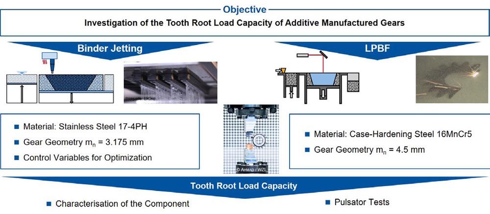
The additive manufacturing processes of BJT and LPBF are intended to enable the production of individualized gears in small batch sizes, through which all requirements with regard to quality, strength, acoustics, and cost-effectiveness can be implemented. The long-term objective is thus to develop a process for the manufacture of highly stressed drive components. More research is still required for this. The objective of this report is to investigate the tooth root load capacity of additively manufactured gears. The BJT and LPBF processes and results are considered independently of each other due to different gear geometry and different material, see Figure 4.
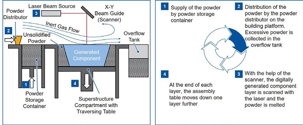
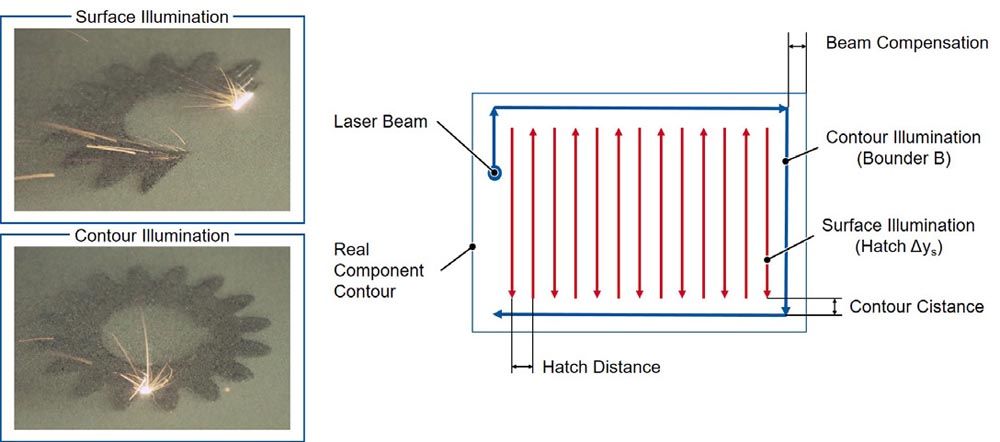
For BJT, the influence of different process variations along the process chain on the tooth root load capacity of BJT gears made of material 17 4PH (stainless steel X5CrNiCuNb16-4) is investigated. The production of various constructive support structures as well as the benefits in the entire process chain are discussed. Various process setting options are explained using the DM P2500 machine from Digital Metal AB. Since an additional heat treatment of the material 17-4PH is not the subject of this work, the gears are ground after sintering, characterized and then examined in screening tests with regard to the tooth root load capacity on the pulsator test rig. The gears produced by LPBF are case-hardened before gear grinding to increase the load capacity. Afterwards, these gears were also ground and examined with regard to tooth root load capacity. The LPBF production process chain and process adjustments are not considered in this report. Only the results on the tooth root load capacity are shown. The BJT gears have a final relative gear density of ρ0,rel ≈ 98 percent, the LPBF gears of ρ0,rel ≈ 99.9 percent.
Control Variables for the Optimization of Binder Jetting Gears
The manufacturing process of BJT gears can be optimized by means of various parameters. In the following chapter, process variations of the powder and binder application are described and the resulting component properties are explained. Subsequently, support structures for gear manufacturing by means of BJT are discussed, which are particularly relevant for the subsequent process steps of heat treatment. Finally, adjustments in the process steps after the printing of the gear foundation are presented.
Powder and Binder Application
During the printing process of the gear green compact, the powder and binder application have been detected as the main influencing factors on the final print result. Since the numerous adjustment possibilities both directly influence the printing result and require an adaptation of the following process steps, knowledge of the respective influences is essential in the process design. Basically, all process information regarding the printing strategy is saved in a print recipe to be generated in advance. The most relevant variables for powder application are the layer thickness (Ds) as well as the application direction and speed as a function of the processed material powder. In addition to the amount of applied binder and the application speed, the application strategy is highly relevant for binder application. The print head must always be calibrated before each print run to minimize system-related errors. Before the powder is filled into the printer and can be applied layer by layer, the powder is mixed. The powder in the build box that is not printed during the BJT process will be recycled after a print and is thus available again for the next print. Typically, a powder mixture for printing consists of one-third new and two-thirds recycled material powder. Before the powder from previous printing processes can be recycled, a sieving process is essential to remove adhesions and larger powder particles. Subsequently, the powder particles are mixed and preheated to 80°C, dried, and filled into the powder magazine, which maintains the temperature at 80°C to ensure flowability.
The layer thickness of the gears made of 17-4PH was Ds = 42 µm. The influence of the layer thickness on the final geometry of the manufactured gears with a number of teeth z2 = 20, a normal module of mn2 = 3.125 mm and a normal pressure angle of αn2 = 20° is negligible. In the case of helical gears, the occurrence of a stair-step effect resulting from the layered printing is possible. The mechanical properties of the gear are directly influenced by the layer thickness. If the layer thickness is too high, the binder cannot completely penetrate the layer and thus reduce the component stability.
The green part density is significantly influenced by the adjustment of the powder application direction and speed. This is an important parameter with regard to the sintering activity of the green compact. A higher green part density implies a lower shrinkage during sintering. This results in a reduction of the induced stresses and a decrease in crack formation, see “Design Support Structures in Gear Manufacturing.” There are two different strategies for applying powder—application in only one direction of motion and application in two directions of motion (outward and backward path above the build box). When applying powder in two directions, a larger quantity of powder is inserted into the powder bed with the same layer thickness and the green part density increases. If the speed is also reduced during powder application, the green part density increases further, but productivity decreases.
In addition to the optimizations in powder application, the part quality can be further increased by adjusting the control variables for binder application. Basically, the binder is applied to the BJT system DM P2500 via two cartridges. The control variables consist of the amount of binder applied to the powder bed and the application speed and strategy. The amount of binder applied can be adjusted by controlling a different number of nozzles (number of pixels) of the respective cartridge. The green part geometry is described in the layer by pixels. Thus, pixels can be eliminated from the binder application based on defined patterns, similar to that of a chessboard.
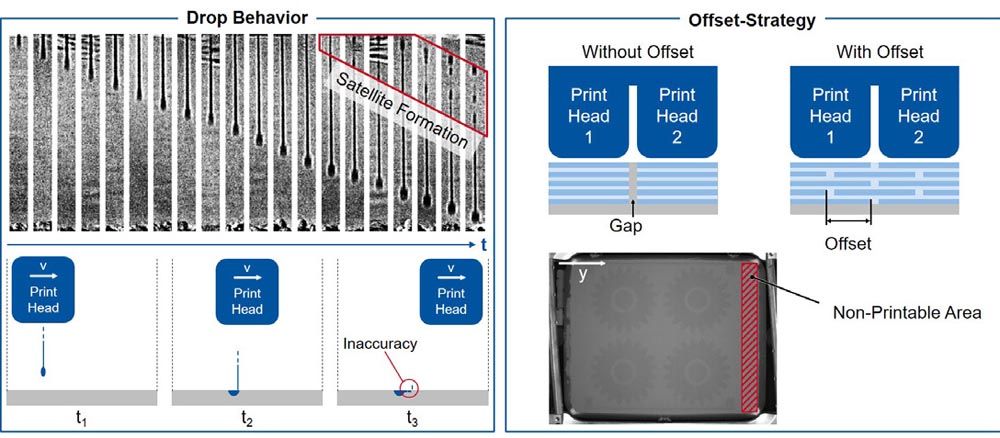
Figure 5—Drop behavior and offset strategy in binder application (Ref. 23).
The image of the drop geometry is shown in chronological order. The spherical drop head is followed by a longer, thin tail at the end of which several smaller drops, so-called satellites, are separated from the main drop. Due to the break in the tail, the satellites drift away from the main drop in the direction of movement of the print head. With increasing horizontal printhead speed, the drift also increases, and the geometric inaccuracy rises (Ref. 23). In order to increase the green part density, the offset strategy is applied when printing the green gear. By overlapping the binder application areas, gaps between the individual print lines are avoided due to the intermediate area of both print heads. Since the offset of the print heads takes place in different powder layers, binder application-related weak points in the component are avoided and the binder is evenly distributed in the green part. The offset is compensated vertically to the direction of movement during binder application. The application of the offset strategy minimizes the print area in the build box due to the risk of component breakage in this area. Furthermore, the starting point of the print head's movement is varied at regular intervals when printing the gears in order to optimize the binder distribution over the entire component height.
Design Support Structures in Gear Manufacturing
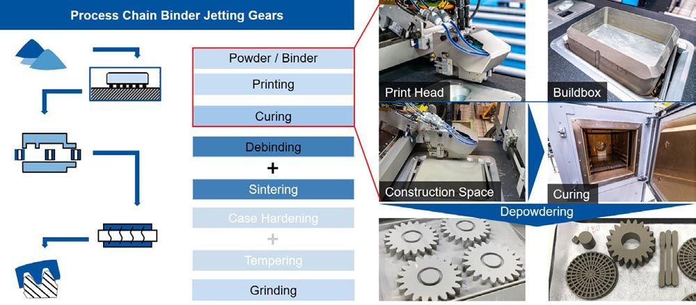
Structural support structures during BJT of gears correspond to small components that are additionally produced with the gear in a printing process. These elements primarily provide support during the post-treatment processes of hardening the binder, known as curing, and sintering. Especially during the two process steps mentioned above, stresses are caused which are reduced by the use of support structures. During curing, the buildbox with the printed gears and the unused, recyclable powder is heated from ambient temperature to the curing temperature TC = 200°C over a defined period of time (tR) immediately after printing. Afterwards the gears remain in the oven at the temperature (TC) for a calculated holding time (tH). The process times in the oven can be calculated by the amount of binder used during printing and the number of layers. Thus, the times are varying for each print. When simultaneously printing four gears made of material 17-4PH, the ramp time is approximately tR = 9 hours and the holding time at TC is approximately tH = 6 hours. The stresses during curing are caused by the static and dynamic interactions of the powder. While the dry pure powder has static characteristics, the printed green compacts have dynamic properties due to the wetting of the powder with the binder. The evaporation of moisture in the green compact causes it to shrink slightly. This results in an increasing pressure of the powder on the bore of the gear, which counteracts the dynamic behavior of the green part. In this manner, stresses can potentially be introduced into the component, which can lead to the formation and propagation of cracks in the green part of the gear. Due to the constructive insertion of a cylindrical green compact in the gear bore, the critical transition area between the statically behaving powder and the dynamic component green compact is reduced and the risk of crack formation during curing is minimized, compare left in Figure 6.
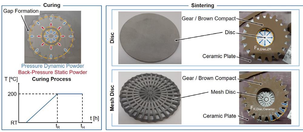
Figure 6—Support structures of the gear for the process steps of curing and sintering.
The cylinder height corresponds to the tooth width (b2), the diameter is slightly smaller than the bore diameter (di) of the gear. This ensures the separation of both elements after curing. The visible gap formation in the outer area of the gear is negligible, as it has no effect on the component and thus to the component quality. After the curing process, the printed green gears are manually depowdered and inspected for component damage before being forwarded to the debinding and sintering process. As shown in Figure 6, support structures are designed and printed for the sintering process as well. During the sintering process, significantly higher stresses can occur compared to curing due to the shrinkage of the gear caused by diffusion processes. If the green gear is sintered directly on the ceramic plate, the area of contact in the sintering furnace, without a support structure, the frictional force between the ceramic plate and the gear counteracts the sintering shrinkage of the gear despite the use of friction-reducing materials. This can lead to cracks on the face surfaces of the gear. The cracks can completely rupture during debinding and sintering and thus lead to the rejection of the gear. In order to prevent this effect, a disc made of the same material and thus with similar shrinkage properties as the gear was constructed on the one hand and a mesh disc on the other, cf. Figure 6. The disc diameter corresponds to the outer diameter of the gear and the thickness is s = 2 mm. The disc does not have a hole in its center and shrinks almost congruently with the gear, which implies a reduction in the frictional force between the gear and the base. A disadvantage due to the continuous disc design is the lack of free spaces, for example a hole, in the radial direction. Thus, at a certain moment during the sintering process, the disc cannot shrink any further and the sintering distortion of the disc begins. At the same time, the shrinkage of the gear continues due to the significantly higher amount of binder. Furthermore, the high weight of the gear causes additional friction between the disc and the ceramic plate. In the worst case, the disc shrinks unevenly, cracks and no longer performs its function as a support structure. For this reason, the disc has been further developed into a mesh disc by means of constructive adaptation following a failure analysis. The outer diameter also corresponds to that of the gear, but the thickness has been increased to s = 5 mm. The design adjustments in the structure resulted in radial free spaces, which considerably increase the deformability in the planar dimension. The contact area is smaller and material no longer counteracts shrinkage. Stress cracks in the gear due to the sintering process are thus avoidable. A further advantage of the mesh disc compared to a disc is on the one hand the increased resource efficiency and on the other hand the possibility of heat dissipation from the gear during the sintering process as well. Convective ambient properties also prevail in the furnace on the bottom side of the gear and the contact surface is smaller.
Post Treatment of Printed Gears
After printing the gears, the applied binder is hardened in the curing process and the gears can be removed from the powder bed, cf. “Design Support Structures in Gear Manufacturing.” Subsequently, the debinding and sintering of the gears is performed. Debinding was conducted in a muffle furnace and sintering in a retort furnace. Due to the size of the furnace chamber, four gears could be fed to the debinding and sintering processes simultaneously. Each gear was positioned upon a ceramic plate including the support structure. A zirconium based lubricant was applied between the support disk and the ceramic plate before debinding. This prevents the gears from sticking to the support structure and the ceramic plate after sintering. Due to the fragility of the gear, it is not possible to apply the lubricant after debinding. Two ceramic plates are stacked on top of each other in the furnaces. Since minor temperature variations can occur in a chamber furnace depending on the location, the positioning in the furnace also influences the gear quality. The temperature variations induce stresses into the gears, which already lead to minimal cracks in the component during debinding and are intensified by the downstream sintering process. In addition, the amount of binder to be evaporated during debinding, analogous to the gear print (see “Power and Binder Application”), influences the component quality. A reduced amount of binder decreases the pressure during evaporation. For gears, which were manufactured with a higher amount of binder than for the final gear print (56.26 percent of the pixels), cracks occurred after debinding depending on the position. The cracks only occurred within the gears positioned at the top. After reducing the amount of binder used in the print and extending the heating ramp (analogous to curing) to approximately TD = 350°C holding temperature, no more component cracks were detected. Further process adjustments of the debinding were not necessary.
During sintering, the required density of the gear is adjusted by the maximum sintering temperature at a constant sintering time. The sintering process is divided into three phases: heating to the final sintering temperature using various holding ramps, holding at the sintering temperature (TS) and defined cooling. The target density of ρ0,rel = 98 percent was iteratively approximated in sintering tests with gears. Externally visible cracking was avoided by the design of the support structure, cf. “Design and Support Structures in Gear Manufacturing.” The respective density was determined by using Archimedean measurements of reference cubes. The maximum sintering temperature of the 17-4PH gears is approximately TS = 1300 °C. Sintering was performed in a pure hydrogen atmosphere to prevent oxidation of the gears during the process.
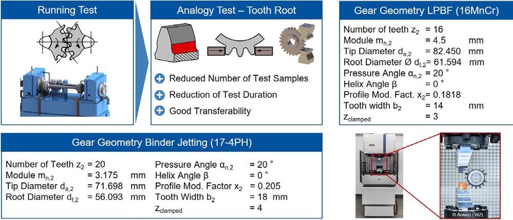
Figure 7—Pulsator test to investigate the tooth root load capacity (Ref. 19).
Tooth Root Load Capacity of Additive Manufactured Gears
The following chapter describes the results of the tooth root load capacity tests of the additively manufactured BJT and LPBF gears. For this purpose, the fatigue strength of BJT gears made of the material 17-4PH was investigated and classified in the state of the art by comparison with cold rolled gears made of 316L. In addition, the fatigue strength of LPBF gears made of the material 16MnCr5 was determined. Before testing, the gear quality and the surface roughness of the BJT and LPBF gears were measured. Due to different materials and gear geometries, the tooth root load capacity results of both processes are not comparable.
Experimental Design and Description
Gear-critical load types are stresses on the tooth flank due to rolling and bending fatigue in the tooth root (Refs. 13, 20, 24). The experimental investigations of the ground gears with regard to the tooth root load capacity were performed at a pulsator test rig. The pulsator is an analogy test rig which approximates a part of the stress curve occurring in tooth meshing with an alternative concept of load application, Figure 7. According to the definition of the ISO 6336 3 standard, the tensile and compressive stresses σZ and σD resulting from the mechanical load reach the maximum at the tooth root in the area of the 30° tangent (Ref. 16).
The major advantage of the pulsator test compared to the running test is the possibility of multiple use of a gear. In addition, no counter gear is required. The number of possible test points depends on the contact line to be examined and the number of teeth z2 of the gear. Both the BJT and the LPBF gear contain four test points. The gear is clamped over several teeth between two plane-parallel pulsator clamps four teeth are clamped at the BJT gear and three teeth are clamped at the LPBF gear. In this way, the tooth normal force from the running test is applied to the gear. One clamp performs a pulsating movement and, in this way, introduces a sine-shaped force curve into the tooth. The other stationary clamp absorbs the applied force. This enables automated control of the pulsator test rig and evaluation of the tooth root load capacity.
Characterization of the Additive Manufactured Gears
Both, the BJT and LPBF gears were profile ground using a Kapp KX 500 Flex gear grinding machine. The Binder Jetting gears made of 174PH were not heat treated, while the LPBF gears made of 16MnCr5 were case hardened before grinding. The gear quality was measured on a Klingelnberg P65 gear measuring machine. Figure 8 shows an example of the results of the gear measurement of the Binder Jetting gears after hard finishing. The results of the LPBF gear measurements are similar, and thus not shown in this report. The measurement was conducted on all available gears in order to achieve the best possible statistical validation of the evaluation. In addition to the profile and helix deviation, the single and accumulated pitch errors fp as well as the radial runout error FR were measured. The measured values were evaluated by using a boxplot diagram. All measured values, both of the BJT and LPBF gears, averaged minimum within IT5 according to DIN EN ISO 1328 (Ref. 6).
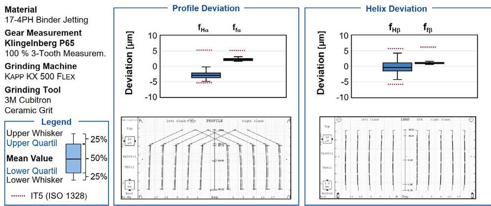
Figure 8—Gear measurements after hard machining of the BJT gears made of 17-4PH.
The surface roughness of the respective tooth profiles of the BJT gears was measured after sintering and grinding using the tactile roughness measuring device Hommel etamic nanoscan 855. The roughness of the LPBF gears was measured after heat treatment and grinding. The evaluation of the roughness values and measurement reports was performed in accordance with DIN EN ISO 4288 in the direction of the profile (Ref. 8). In total, eight roughness measurements were performed for each gear. Of four teeth evenly distributed over the circumference, a roughness measurement was taken on both the right and the left flank of the respective tooth. The mean value of all Rz measurements was Rz = 35.8 µm for BJT gears after sintering, and the arithmetic average roughness value Ra = 6.6 µm. Hard finishing achieved a roughness to Rz = 2.3 µm and Ra = 0.3 µm. The mean value of all Rz measurements was Rz = 26.5 µm for LPBF gears after heat treatment, and the arithmetic average roughness value Ra = 4.7 µm. Hard finishing achieved a roughness as well of Rz = 1.47 µm and Ra = 0.2 µm. The roughness of the ground tooth roots of all the gears examined was within this range as well.
Investigation of the Tooth Root Load Capacity of Binder Jetting Gears
In order to describe the tooth root load capacity, 14 tests were performed at the transition to the fatigue strength load range using the stair-step method (Ref. 9). The staircase method was evaluated according to Hück (Ref. 15). The load step of the fatigue strength range of the BJT gears is shown in Figure 9. The fictitious point formed the 15th test point. The load step increase per double amplitude was ∆FA = 1 kN. The ratio of step jump and standard deviation was calculated according to Hück (Ref. 15). The limiting number of oscillations for the tooth root load capacity is set to NG = 3∙106 load cycles (LC) according to DIN ISO 6336 part 3 (Ref. 16).
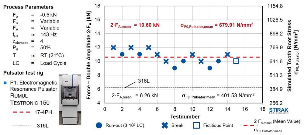
Figure 9—Fatigue limit for BJT gears according to Hück (Ref. 15).
This also ensures comparability with the results of other projects and materials. Termination criteria during the pulsator test are, on the one hand, reaching the limit number of load cycles and, on the other hand, tooth root fracture (Ref. 19). According to the Hück stair-case method, the following test depends on the previous test result. In the case of a tooth root fracture before reaching the limit number of load cycles NG, the load or the stress is reduced by one step (∆FA = 1 kN) and in the case of a run-out, it is increased by one step (Ref. 15). The y-axis shows on the one hand the force FA of the double amplitude, which indicates the stress range, and on the other hand the tooth root stress σF0 calculated by Stirak. The tooth root stress describes the local load in the tooth root. The test frequency of the pulsator test rig was fP1 = 143 Hz. Mean value of the endurable double amplitude (fatigue strength, NG = 3∙106 LC) was 2∙FA,mean = 10.60 kN, corresponding to an endurable tooth root stress of σF0 = 679.91 N/mm2. The mean value of the double amplitude corresponds to the fatigue strength characteristic value for a failure probability of Pa = 50 percent. The standard deviation was σ = 2 percent. In addition, the average mean value of the double amplitude and the calculated tooth root stress of the fatigue strength tests of gears made of 316L are shown as a reference. Due to the material characteristics and sintering cycles deviating from 17-4PH, these gears were recompacted at a relative core density ρ0,rel,2 ≈ 92 percent by means of external transverse rolling to compact the highly loaded surface zone. For this purpose, the rolling machine Profiroll PR 15HP was used. The average mean value of the endurable double amplitude was 2∙FA,mean = 6.26 kN, corresponding to an endurable tooth root stress of σF0 = 401.53 N/mm2. The comparison of the load capacity results of not densified gears made of 17-4PH with load capacity results of densified gears made of 316L (stainless steel X2CrNiMo17-12-2) showed an increase of almost 70 percent. Furthermore, no pores were recognizable on the microscopic images of the fracture surfaces. Basically, the crack initiation was causally related to the failure in the tooth root area at the surface of the 30-degree tangent. Within the BJT batch, minor scattering of results and achieved load changes occurred depending on the furnace position during sintering. Gears placed in the rear part of the furnace achieved higher load levels. It was notable that some tooth root fractures only occurred after more than two million load cycles.
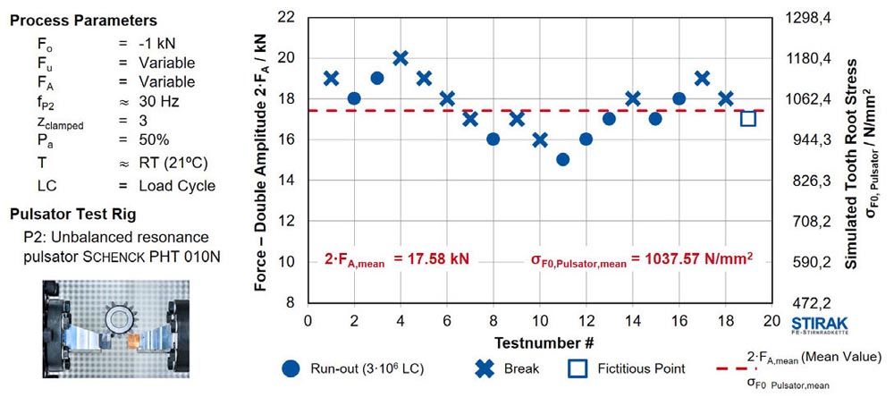
Figure 10—Fatigue limit for LPBF gears according to Hück (Ref. 15).
Investigation of the Tooth Root Load Capacity of LPBF Gears
The investigation of the tooth root load capacity of the LPBF gears was done similarly to that of the BJT gears, see “Investigation of the Tooth Root Load Capacity of Binder Jetting Gears.” 18 tests were performed at the transition to the fatigue strength load range using the staircase method (Ref. 9). The fictitious point formed the 19th test point. As with the BJT gears the load step increase per double amplitude was ∆FA = 1 kN. The stair step of the fatigue strength range of the BJT gears is shown in Figure10. The test frequency of the pulsator test rig was fP2 = 30 Hz. The different test frequencies of the pulsators fP1 = 143 Hz at BJT and fP2 = 30 Hz at LPBF do not influence the results, as both fP1 and fP2 are below 200 Hz (Ref. 17). Mean value of the endurable double amplitude (fatigue strength, NG = 3∙106 LC) was 2∙FA,mean = 17.58 kN, corresponding to an endurable tooth root stress of σF0 = 1037.57 N/mm2. The mean value of the double amplitude corresponds to the fatigue strength characteristic value for a failure probability of Pa = 50 percent. The standard deviation was σ = 2 percent.
Summary and Outlook
In this report, the potential of gears manufactured by both BJT, using the material 17-4PH (stainless steel X5CrNiCuNb16-4), and LPBF, using the case hardened steel 16MnCr5, was analyzed with regard to the tooth root load capacity at a relative density of ρ0,rel ≈ 98 percent (BJT) and ρ0,rel ≈ 99.9 percent (LPBF). Since an additional heat treatment of the material 17-4PH was not the purpose of this work, the gears were ground after sintering, characterized and subsequently investigated in screening tests on the pulsator test rig. The manufacturing of various support structures as well as their benefits were discussed. These elements primarily provide support during the post-treatment processes of curing, as well as debinding and sintering and minimize the risk of fracturing. During curing, the stresses are induced by the static and dynamic interactions of the powder. The process stability of debinding and sintering was significantly increased by the use of a mesh disk between the gear and the ceramic sintering base. Effects of the sintering furnace on the printing result, especially if a retort furnace is used, also have to be considered. During the printing process of the green part, the powder and binder application have been identified as the main influencing factors on the final print result. In addition to the amount of binder applied and the application speed, the application strategy is highly relevant. The green part density is significantly influenced by the setting of the powder application direction and speed. The reduction of the binder amount shortens the process times and decreases the risk of cracking. The production parameters of LPBF gears were not considered in detail in this report.
The quality of the gears was measured after grinding using a gear measuring machine. All measured values averaged within quality class IT5 according to DIN EN ISO 1328 (Ref. 6). Mean value of the endurable double amplitude (fatigue strength, NG = 3∙106 LC) of the BJT gears was 2∙FA,mean = 10.60 kN, corresponding to an endurable tooth root stress of σF0 = 679.91 N/mm2. The comparison with load capacity results of densified gears made of 316L (stainless steel X2CrNiMo17-12-2) showed an increase of almost 70 percent. Within the BJT batch, minor scattering of results and achieved load changes occurred depending on the furnace position during sintering. Gears placed in the rear part of the furnace achieved higher load levels. The mean value of the endurable double amplitude (fatigue strength, NG = 3∙106 LC) of the LPBF gears was 2∙FA,mean = 17.58 kN, corresponding to an endurable tooth root stress of σF0 = 1037.57 N/mm2. Due to different materials and gear geometries, the tooth root load capacity results of both processes are not comparable.
The long-term objective is to reduce and optimize support structures in Binder Jetting gear manufacturing. The influences of the position dependency during sintering in the retort furnace on the load capacity of each individual gear can be reduced to a minimum by using a continuous furnace. In short term, comparable investigations with regard to creep strength and fatigue strength has to be repeated in a continuous furnace in order to be able to provide a well-founded statement about the tooth root load capacity of BJT gears made of 17-4PH. Furthermore, an additional heat treatment shall be tested in order to further increase the tooth root load capacity. The influence of variable binder moistening and different layer thicknesses on the mechanical properties will be investigated on bending and compressive specimens. Furthermore, the development and certification of further materials, especially common gear steels such as 16MnCr5, is planned for the BJT. These can already be processed with the LPBF. The aim of the LPBF developments is to significantly increase process quality and stability by using process monitoring methods.
Acknowledgement
The authors gratefully acknowledge financial support by the WZL Gear Research Circle for the achievement of the project results.
This paper was first presented at the 9th WZL Gear Conference in the USA, held July 2022 in Itasca, IL. It is reprinted here with permission.

References
- Andersen, O.; Studnitzky, T.; Hein, S.; Riecker, S.; Quadbeck, P.; Petzold, F.; Kieback, B.: Neue Entwicklungen auf dem Gebiet der nicht-strahlbasierten additiven Fertigungsverfahren. In: Tagungsband zur Hagen, 29./30. November. Dortmund: Heimdall, 2018, S. 255–280.
- Beiss, P.: Pulvermetallurgische Fertigungstechnik. Berlin: Springer Vieweg, 2012.
- Bergs, T.; Brimmers, J.; Klee, L.: Binder Jetting. PM Gears in Small Series Production. In: Müller, B. (Hrsg.): Fraunhofer Direct Digital Manufacturing Conference DDMC 2020. Stuttgart: Fraunhofer Verlag, 2020.
- Brecher, C.: Integrative Produktionstechnik für Hochlohnländer. Berlin: Springer, 2011.
- Buchbinder, D.: Selective Laser Melting von Aluminiumgusslegierungen. Diss. RWTH Aachen, 2013.
- Norm ISO 1328 Teil 1 (September 2013) Cylindrical gears. ISO system of flank tolerance classification. Definitions and allowable values of deviations elevant to flanks of gear teeth.
- Norm DIN EN ISO / ASTM 52900 (June 2017) Additive Fertigung—Grundlagen—Terminologie.
- Norm DIN EN ISO 4288 (April 1998) Regeln und Verfahren für die Beurteilung der Oberflächenbeschaffenheit.
- Dixon, W.; Mood, A.: A Method for Obtaining and Analyzing Sensitivity Data. In: J. Am. Stat. Assoc., 241. Jg., 1948, Nr. 43, S. 109–126.
- Dutta, B.: Science, technology and applications of metals in additive manufacturing. Amsterdam: Elsevier, 2019.
- Gebhardt, A.: Generative Fertigungsverfahren. Additive Manufacturing und 3D Drucken für Prototyping—Tooling—Produktion. 4., neu bearb. und erw. Aufl. München: Hanser, 2013.
- Gebhardt, A.; Kessler, J.; Thurn, L.: 3D-Drucken. Grundlagen und Anwendungen des Additive Manufacturing (AM). 2., neu bearb. und erw. Aufl. München: Hanser, 2016.
- Haberhauer, H.: Maschinenelemente. Gestaltung, Berechnung, Anwendung. 18., bearb. Aufl. 2018. Aufl. Berlin, Heidelberg: Springer Verlag, 2018.
- Höganäs Group Company (Digital Metal): Materials for 3D printing. Höganäs.
- Hück, M.: Ein verbessertes Verfahren für die Auswertung von Treppenstufenversuchen. In: Werkstattstech. online, 24. Jg., 1983, S. 406–417.
- Norm ISO 6336 Teil 3 (September 2006) Calculation of load capacity of spur and helical gears. Calculation of tooth bending strength.
- Issler, L.; Häfele, P.; Issler-Ruoß-Häfele; Ruoß, H.: Festigkeitslehre—Grundlagen. 2. Aufl. Berlin: Springer, 2006.
- Klocke, F.: Fertigungsverfahren 5. Gießen, Pulvermetallurgie, Additive Manufacturing. 4. Aufl. Berlin: Springer, 2015.
- Klocke, F.; Brecher, C.: Zahnrad- und Getriebetechnik. Auslegung—Herstellung—Untersuchung—Simulation. 1. Aufl. München: Hanser, 2017.
- Kotthoff, G.: Neue Verfahren zur Tragfähigkeitssteigerung von gesinterten Zahnrädern. Diss. RWTH Aachen University, 2003.
- Krauss, H.: Qualitätssicherung beim Laserstrahlschmelzen durch schichtweise ther-mografische In-Process-Überwachung. Diss. Technische Univer-sität München, 2016.
- Meiners, W.: Direktes selektives Laser-Sintern einkomponentiger metallischer Werkstoffe. Diss. RWTH Aachen, 1999.
- Parab, N.: Real time observation of binder jetting printing process using high-speed X-ray imaging. In: Scientific reports, 2019, Nr. 1, S. 2499.
- Schlecht, B.: Maschinenelemente 2. Getriebe—Verzahnungen—Lager. München: Pearson Studium, 2010.
- Verband Deutscher Maschinen- und Anlagenbau e.V.: Antrieb im Wandel. Die Elektrifizierung des Antriebsstrangs von Fahrzeugen und ihre Auswirkung auf den Maschinen- und Anlagenbau und die Zulieferindustrie. Bd. Nr. 2018, Frankfurt a.M.
