Bevel gears are widely used in various industrial applications, such as automotive, aerospace, and marine industries, due to their ability to transfer power between non-parallel shafts. The conventional manufacturing of bevel gears involves several time-consuming and costly processes, including gear blank preparation, gear cutting, and gear finishing. The increasing demands on gear components regarding increasing power density, reducing installation space, reducing weight, and increasing efficiency are also reflected in the design of gear components. The reduction of installation space and weight as well as the increase in power density often leads to an optimized wheel body design that interacts with the gearing in terms of load capacity and stiffness. This leads to an increase in the required geometric degrees of freedom (DOFs). Due to the resulting complex wheel body shapes and different production-related effects, production-related geometry adjustments may also be necessary. Tools for evaluating the gearing in combination with the wheel body shape and its influences nowadays form the basis for unlocking the holistic optimization potential of transmission components.
Based on these high requirements for the gearing, the model for calculating the load-bearing capacity must not fall short. With the help of the FVA program package BECAL, it is possible to carry out a tooth contact analysis based on the exact geometry with very high accuracy. Thus, in contrast to standardized, simplified calculation methods (Ref. 1), microgeometry is included in a load distribution calculation and local load capacity verification is possible.
In this article, we introduce the STEP import feature of BECAL and review the underlying theoretical approaches. In addition, fields of application are identified and finally illustrated with an explicit use case. The use case in this article is a freeform pre-milled large bevel gear on which production-related geometry adjustments have been applied. We will explore various approaches to manipulating the geometric DOFs and their impact on the final gear geometry. Also, the results of the underlying calculation without production-related geometry adjustments are compared with the results including the geometry adjustment. The BE- and FE-Method are used for calculation and the differences in the results are discussed. The results of this study provide valuable insights into the use of higher-order calculation methods and free-form milling for the bevel gear design and manufacturing process and contribute to the advancement of the manufacturing industry.
BECAL Methodology and Theory
The programme package BECAL (BEvel gear CALculation) has been developed for several decades at the Chair of Machine Elements on behalf of the FVA (Research Association for Drive Technology). Starting from a manufacturing simulation, it maps the complete tooth contact by means of a simulation of the same. By simulating the manufacturing process, the calculations are based on the exact geometry. The flank topography determined point by point is combined into a compensation surface, which is used for the load-free rolling simulation. The results of this simulation are the contact lines and the corresponding contact distances. These are used in the load distribution calculation. The necessary deflections are split into linear and non-linear influence numbers. The linear compliance is determined numerically with BEM or FEM, the non-linear contact stiffnesses are based on Hertzian theory. The load distribution calculated in this way is calculated locally for each flank point and forms the basis for the local load capacity verifications against pitting, micropitting, scuffing and tooth root fracture. This local calculation is based on a local usage of well-known and validated standards like ISO 10300 (Ref. 1) and FVA 411 (Ref. 11). Figure 1 shows the basic calculation procedure of BECAL.
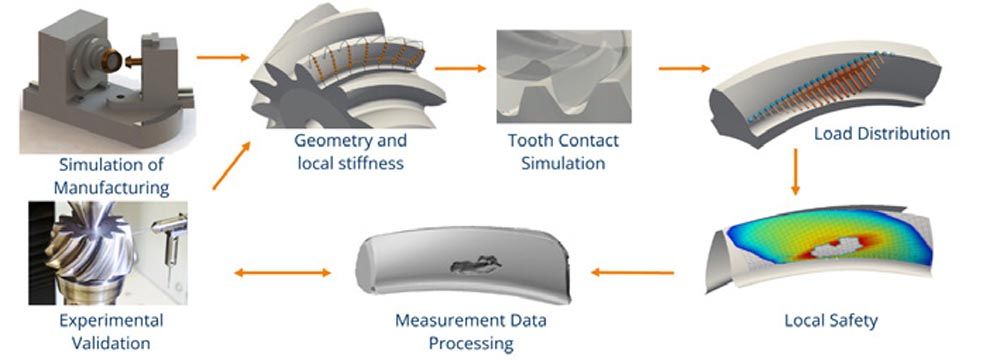
If the bevel gear is not manufactured using the cutter head process, but is free-form milled or forged, for example, the exact geometry of the gears must be specified point-by-point or via a STEP file. Via the standardized STEP interface, the gear geometry can be read directly into BECAL. Flanks and root surfaces can be recognized via a feature designation and approximated by means of compensation surfaces. These are then used for the tooth contact simulation as described above.
Due to the higher degrees of freedom with this type of geometry import, forging in the heel and toe area can also be mapped. However, this means that simplified approaches such as the combination of 2D BEM and analytical regression for the width load distribution according to Schaefer [9] lose their validity. In BECAL, therefore, a possibility was created to calculate the linear influence figures (compliance due to bending, thrust, pressure, and the wheel body) by means of FEM in a generally valid way. The calculation of the non-linear contact deformation can remain unchanged, as this only has significant effects in the close range.
An influence number method can also be used to infer the root stress from the load distribution. For this purpose, as with the determination of linear compliance, singular loads are imposed on the FEM model. To eliminate the influence of the singularities, the same model is calculated with a restraint in the center of the tooth, and the deformation results are subtracted from the first model. Here, however, the entire tensor of the root stresses at each node must be stored and not just the deformation along the direction of the force as in the case of yielding in contact. After calculating the load distribution, the "influence tensors" can be superposed based on the respective loads.
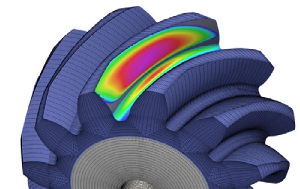
This method, starting from a STEP model, via influence numbers by FEM and contact stiffnesses via an extended Hertzian theory, makes it possible to calculate the load distribution and, based on this, also the root stress distribution of almost arbitrarily shaped bevel gears with very high precision. To prove these accuracies, many FEM contact calculations were carried out, which served as a reference for a corresponding comparison (Ref. 10). Maximum deviations in the range of a few percent always occurred in the load distribution. Qualitative distribution of flank pressure and tooth root stress based on FEM influence numbers and influence vectors calculation are shown in Figure 2.
Use Case
In the following, an application of the load capacity evaluation via BECAL’s STEP import is presented using the example of a free-form pre-milled bevel gear set.
Through developments in the fields of tools, processing machines, and strategies, freeform milling has emerged as a promising alternative manufacturing method that can also produce gears with high accuracy and efficiency (Refs. 2–7). Free-form milling is a five-axis machining process that enables the production of complex geometries with a high degree of flexibility. One of the key advantages of freeform milling is the ability to manipulate the geometric degrees of freedom (DOFs) to achieve the desired gear geometry. The geometric DOFs include the tooth profile, tooth surface orientation, tooth surface curvature, and tooth thickness. The manipulation of these DOFs is critical to producing gears with high accuracy and efficiency. Due to the possibility of process integration and the possibility of manufacturing on universal machines and with the use of standard tools, free from milling offers great potential in the field of single-part, small-series, and prototype production.
As already mentioned, in addition to load-bearing capacity-related changes, production-related geometry adaptations can also be made. Such adjustments may be necessary to accommodate deviations that occur during the manufacturing process or to optimize manufacturing processes in terms of processing time. Especially for large components, the issue of heat treatment and the associated changes in volume and shape must be considered. The flatness deviation resulting from the heat treatment can be in the millimeter range for large ring gears. To prevent this deviation, a negative root allowance or a root taper adjustment can be made.
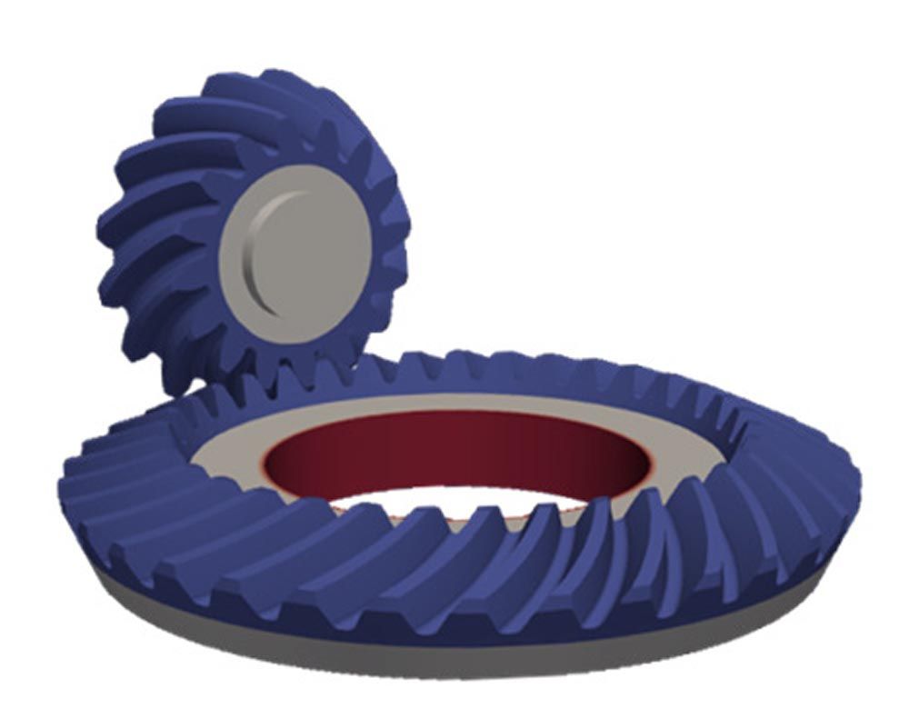
For gears that are ground after heat treatment, a pre-machining close to the final contour can be used to optimize the stock allowance distribution and therefore reduce the material to be removed at the finishing process. The use of a protuberance can also reduce the risk of grinding burn and grinding notches in the tooth root area. The tooth root area can also be optimized in terms of manufacturability and cost. For example, the use of a circular radius can reduce the number of milling paths required and thus the machining time compared to a rolled root geometry. In addition, the process parameters that determine accuracy and machining time, such as step over, feed rate, etc. can be adapted to different gear areas according to their requirements to reduce machining time. In addition, topological tooth root optimization could be implemented by free-form milling. Figure 3 shows an example of a bevel gear set in which the tooth root area has been adjusted due to manufacturing reasons and on which the different functional areas tooth flank (blue), bearing point (red), and gear body (gray) are highlighted in color.
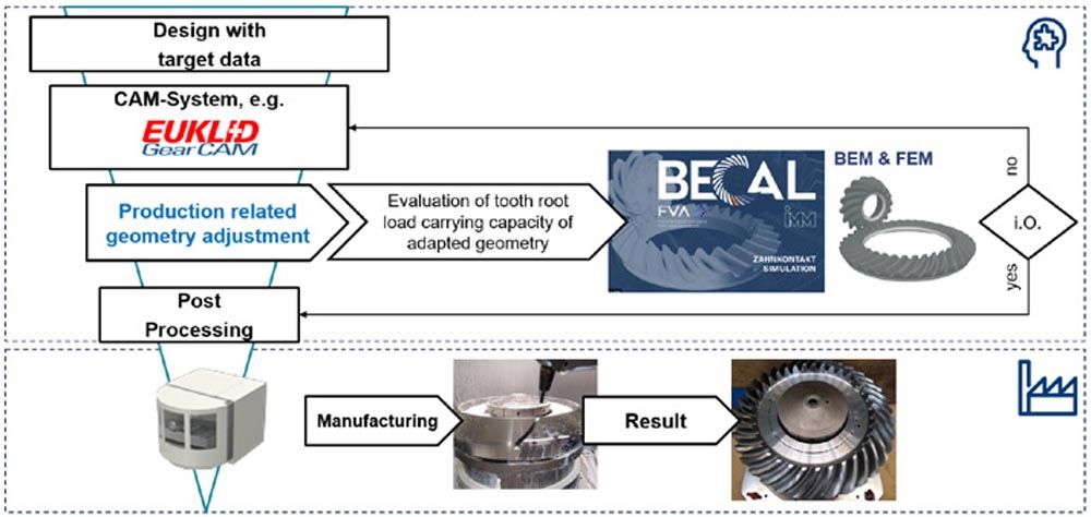
If production-related changes are made to the gearing or the wheel body, these must be evaluated regarding their influence on the load-bearing capacity. Figure 4 shows the basic process of how such an evaluation process could look like. In the following example, Euklid GearCAM was used as CAM-system because it is a very versatile solution for 5-axis gear machining (Ref. 8).
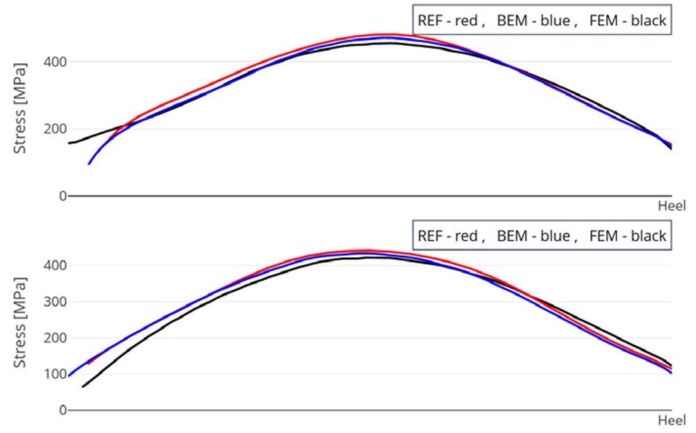
The application example considered here is a large bevel gear used in a marine application which is pre-machined by freeform milling and finished by peeling in the hard state. The tooth root area was adapted for manufacturing reasons (e.g., protuberance) to withstand the changes in shape and volume resulting from heat treatment and optimize the hard machining process. To evaluate the influence of this production-related geometry adaptation, the results of the standard design are compared with those of the adapted geometry via the above-mentioned BECAL STEP import. Since only the tooth root area was adapted, only the tooth root safety is discussed below. The underlying load case is a fictitious load case to demonstrate the calculation method. Results of the tooth root stress and consequently safeties are scalable depending on the load. In the first step, the results calculated using the BE method are discussed and compared with the results of the FE method. Figure 5 shows the course of the tooth root stress over the tooth width.
The course of the tooth root stress was not negatively influenced by the production-related geometry adjustments. A reduction in tooth root stress can be observed due to the choice and execution of the adjustments. This reduction in tooth root stress leads to a calculated increase in safety of between 9 and 13.5 percent. The results of the different calculation variants are summarized in Table 1.
The difference found here between the two calculation methods can be attributed to the simplified distribution of the stress in the width direction. While the stress distribution in the calculation with the FEM is precisely calculated numerically in both the height and width directions, a numerical calculation only takes place in the height direction in the BE-based method. Here, a simplified analytical approach is used in the width direction, which cannot represent all geometric influences.
Summary and Outlook
The results presented were able to show that via the STEP import in BECAL, the load capacity evaluation considering the wheel body influences and high DOFs of transmission components via higher-order computational methods such as BEM and FEM offers a suitable solution. In addition, the advantages of free-form milling were demonstrated by means of a suitable application case. Furthermore, the load-bearing capacity can be positively influenced by a suitable execution of production-related geometry adjustments in addition to the manufacturing process. This offers great optimization potential.
References