(2)
Overall efficiency affects the amount of electric power needed, which in turn determines the battery storage requirements. That means the range for electric cars can be very much improved if you increase overall efficiency. More detail and an explanation for the overall efficiency and the range increase can be seen in Refs. 1–4.
Characteristic Values for Ratio and Ratio Range for Transmission
Starting Gear Ratio
The starting gear ratio istart E can be calculated from the required torque for one axle (or more for four wheel-driven cars) and the torque of the driving motor. You or the applicant decide if you use the normal torque or the peak torque of your electric motor. The axle torque depends on the inertia of the electric motor and the driveline; more detail can be found in Ref. 7, this factor is called φ.


(3)
Taxle=torque at axle [Nm]
TE=torque of electric motor [Nm]
φ=inertia factor (Ref.7)


(4)
maxle=mass of axle [kg]
μwheel=friction coefficient tire-street
rtires=radius of tires [m]
g=earth acceleration [m/s2]
And the inertia factor φ for this example, which is defined from Lechner/Naunheimer (Ref. 7):


(5)
For this example, the mass for one axle will be named to 1,100 kg and the friction coefficient for the contact rubber (wheel) to street will be named to μwheel = 1 and the radius of the tires should be 0,3 m, for this example the istart E can be calculated with Equation 3 to:

(6)
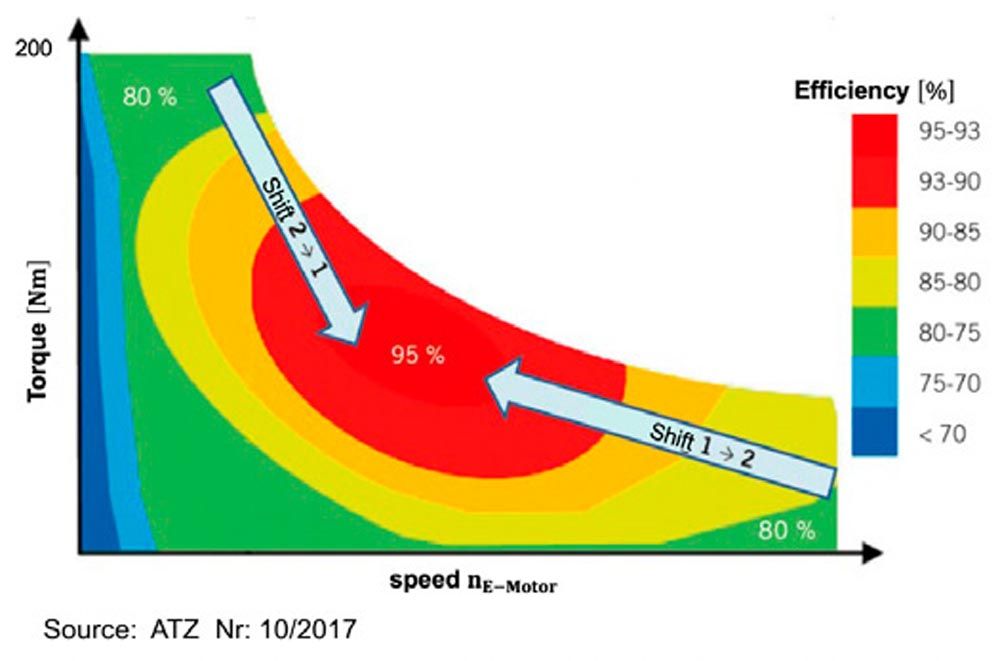
for TE, the value will be taken from the ideal motor out of Figure 2, TE ≈ 200 Nm. For the peak torque of the electric motor, the value becomes smaller.
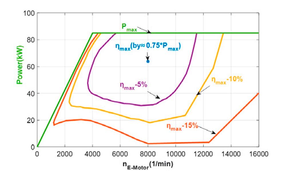
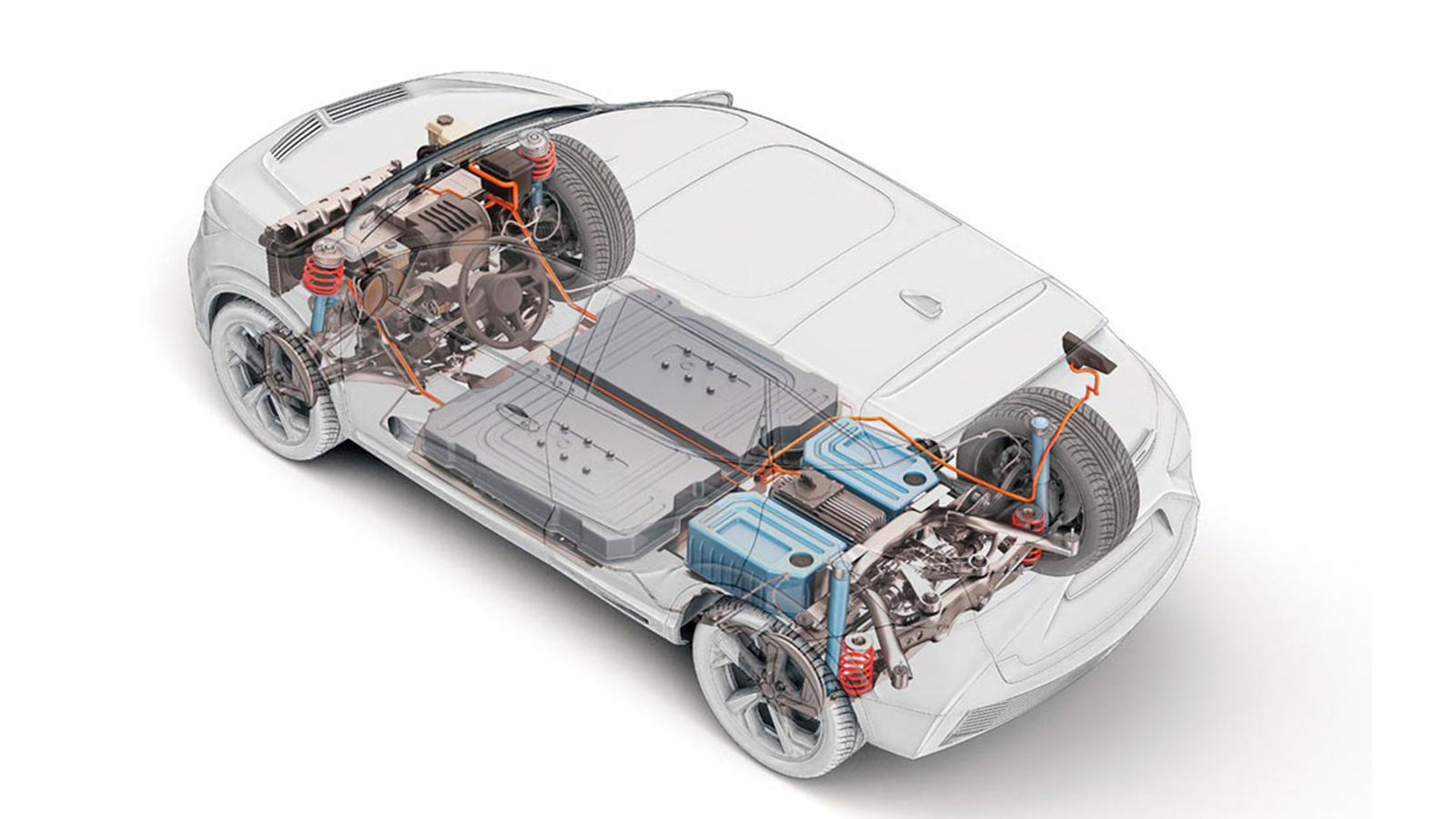
Figure 2—Efficiency map of an electric motor with 85 kW ref. to Figure 1, incl. power unit.
Figure 3 shows the ideal electric motor in a car with a given driving resistance curve (one can use a lot of parameters, which are valid for this curve). The driving resistance curve shows the required power of a car versus car speed. The slipping limit (maximum power) can be calculated with the multiplication of the maximum torque at the axle with the speed of the tires. You can see that, with a starting ratio of about istart E ≈16, the car can only drive about v ~ 105 km/h. Whether this value istart E≈19.4 will be used for maximum acceleration or hill climbing or hill climbing with trailer has no influence. Not until a speed of about 26 km/h can this car accelerate with slipping limit, for acceleration at higher speed you need more power, that is shown in Figure 3.
High-speed Gear Ratio
The high-speed gear ratio iHE can be calculated kinematically (not with torque like starting ratio). The values can be calculated out of maximum speed of the electric motor (nmax) and the required maximum speed of the car (speed of the tires nwheelvcar).


(7)
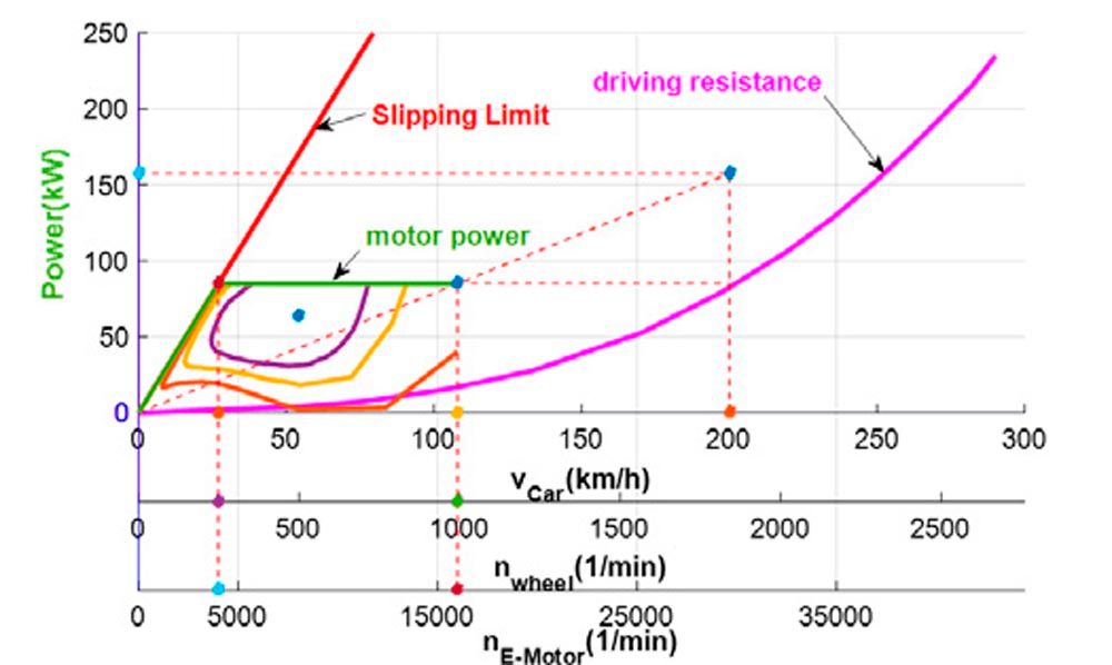
Figure 3—Efficiency-map of an electric motor with a starting ratio for cars.
The theoretic possible maximum speed of the electric motor is 16,000 min-1 (for the example out of Figure 2) and for the maximum speed of the car (for this ideal electric motor with 85 kW, see Figure 4) with Equation 6 can the value calculated to the highspeed gear ratio:


(8)
Of course, one can use other high speeds for cars too.
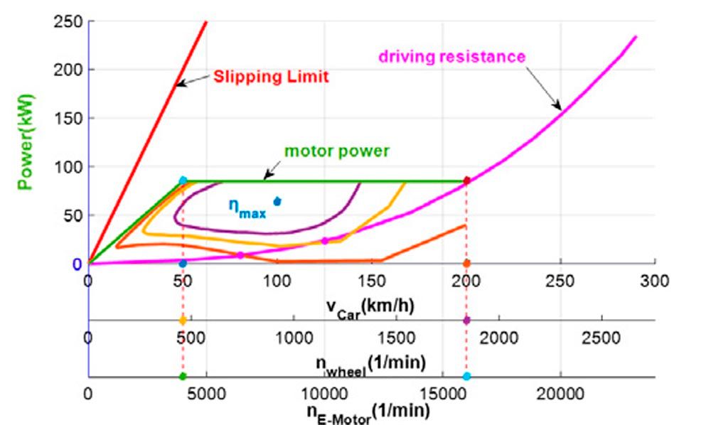
Figure 4—Efficiency-map of an electric motor with a high-speed gear ratio for cars.
With these two values for starting gear ratio and high-speed gear ratio the ratio range of the transmission can be calculated to:


(9)
Overdrive Gear Ratio
The overdrive gear ratio for cars with ICEs can be established with the wish to improve the overall efficiency with Equation 2 and to reduce fuel consumption. For ICEs, this map can be derived from the be-map (specific fuel consumption by an ICE). With one or more overdrive gears you can reduce fuel consumption for lower speeds than the maximum speed of cars.
In principle, you can define overdrive gears for electric cars in the same manner as ICEs. Here you can reduce the electric energy (stored in a battery) the customer requires for mechanical power with better overall efficiency according to Equation 2. Because the efficiency map for electric motors is totally other than for an ICE the following method is proposed. For this ideal electric motor will be proposed in Figure 5 that the driving resistance curve should be tangential to the curve ηmax-5%. This proposal is founded because the theoretical possibility to reduce the electric motor speed more, that means the driving resistance curve should go through the maximum efficiency point (possible for this example for a car speed of about 180 km/h) will result a very low value of the overdrive gear and a very high value of the ratio range for the transmission.
With this proposal you will get Figure 5, marked with x for a car-speed of 150 km/h and a speed for the electric motor of about nE-Motor ≈ 9700 min-1:


(10)
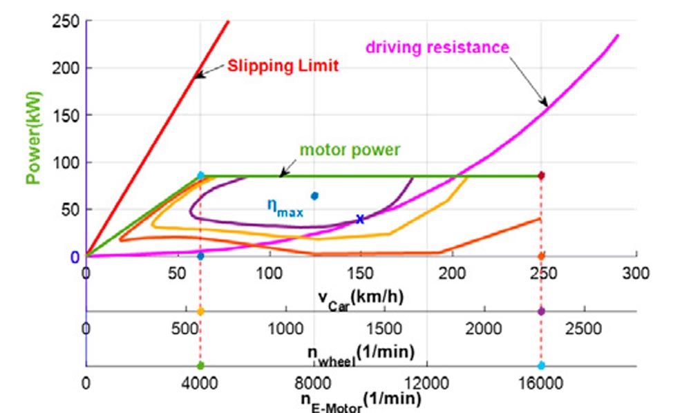
Figure 5—Efficiency-map of an electric motor with an overdrive gear ratio for cars.


(11)


(12)
Ratio Range for Transmission
The ratio range for this example can be derived out of driving resistance curve for cars and efficiency-maps for the engines. This can be electric motors or ICEs. For calculation of the ranges following equation can be used:


(13)

 (14)
(14)

 (15)
(15)
Two-Speed-Automatic Transmission for Electric Cars
If an electric car is designed to have only two ratio ranges, the high-speed gear ratio becomes less relevant, because electric motors can produce the maximum power by smaller and lower speeds (Figure 1 and Figure 2). The range Φtr for this example is very high and the step from first gear to the second gear are unusual and for shifting elements too high. Therefore, it is recommended to use the peak-torque of electric motors to reduce the ratio range. The value of the starting gear ratio will be decreased, though that Φtr will become much smaller and suitable for shifting elements. Nevertheless, the ratio range for transmission is smaller than for all known electric motors (Equation 1), which means, if you shift at the high speed of the electric motor after the shifting process you have the same power as before. For calculation of brakes/clutches you should have a look at the patents (Refs. 8, 9).
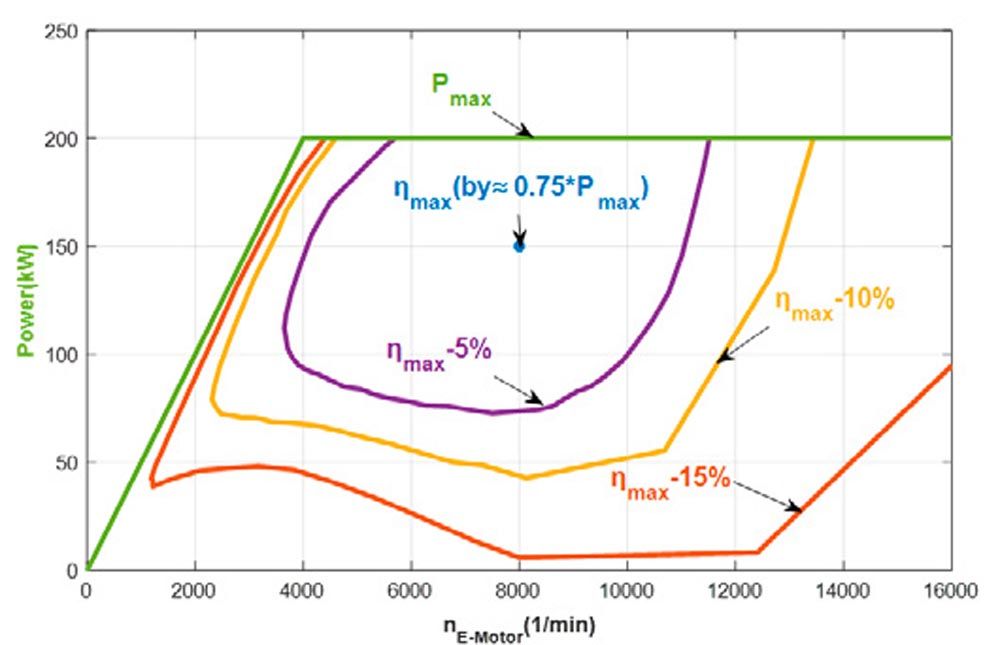
Figure 6—Efficiency-map of an electric motor with 200 kW ref. to Figure 1, incl. power unit.
In Figures 6 and 7, the ideal motor is scaled up to a power output of 200 kW, using the data from either Figure 1 or Figure 2. For this particular electric motor, the required gear ratio for driving is approximately 1, eliminating the need for a second ratio. This is because the car can achieve speeds exceeding 200 km/h using just the starting gear, as demonstrated in Figure 7. If you aim for higher overall efficiency through overdrive, a two-speed automatic transmission would be beneficial.
Figure 8 displays the overall efficiency, calculated using Equation 2. Compared to the smaller 85 kW electric motor, the efficiency has decreased by about 5 percent because the motor’s optimal efficiency point is not achievable at a constant driving speed. Data points for speeds of 80 and 130 km/h (50 mph and 85 mph) are plotted in Figures 7 and 4. For the electric motor with 85 kW the value of η is ≈ ηmax – 10 percent, for 200 kW this value is η is ≈ ηmax – 15 percent. In the calculations using Equation 2, the transmission efficiency has only a minor impact. When comparing the efficiency of current mass-produced models with the patented example, it is evident that transmission efficiency does not have a significant influence, although it is better than a one-speed transmission.
For the curves in Figure 8, the efficiency of the transmission was taken constant (equal for both transmissions), because losses in the open synchronization (Ref. 12) exist and they are about the same value as the lower losses of the chosen planetary transmission. Figure 8 shows only the difference of ηmot (Equation 2) between the different electric motors with 85 kW and 200 kW. The advantages in efficiency are direct advantages in the range of electric cars.
Here it can be seen that “high-powered” cars have nearly 5 percent lower range by the same size of the energy-storage (battery). High-powered cars are for example the B-class (like corsa/ fiesta /polo) with 200 kW power. This class should be powered by 85 kW and 2-speed-automatic transmission, then you have advantages in the range of these classes and the same hill-climbing possibility and the same acceleration until about 25 km/h. That means nearly no disadvantages.
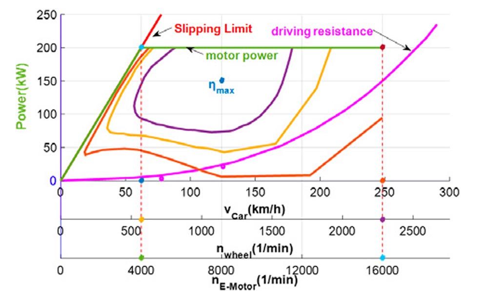
Figure 7—Efficiency-map of an electric motor (200 kW) with a starting ratio for cars.
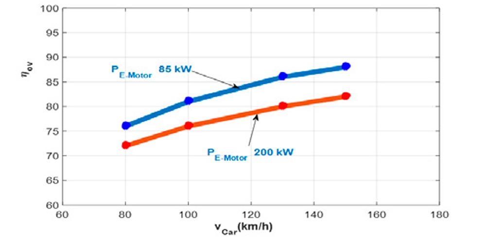
Figure 8—Overall efficiency for constant speed for different power of the electric motors.
The Example for the 2-Speed Transmission
Figure 9 shows the sketch out of the patent. The electric motor is connected to the sun 1 of the two used planetary transmission. The first gear (starting gear) uses the planetary transmission 1–2 with a stepped planet, the second gear (highspeed-gear) is the “normal” planetary transmission with 1–2. That means the carrier is by both gears connected to the output-shaft. With the two brakes, one is connected to the smaller ring-gear 2’ the other one is connected to the bigger ring-gear 2. For both planetary transmission the efficiency can be calculated with (Ref. 11) with the working sheets for η1s. One part of the power is transmitted as clutch-power without any losses (Ref. 11).
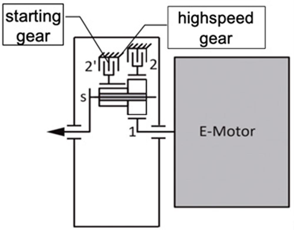
Figure 9—Sketch of the planetary transmission out of Pat. PCT/EP2020/079280.
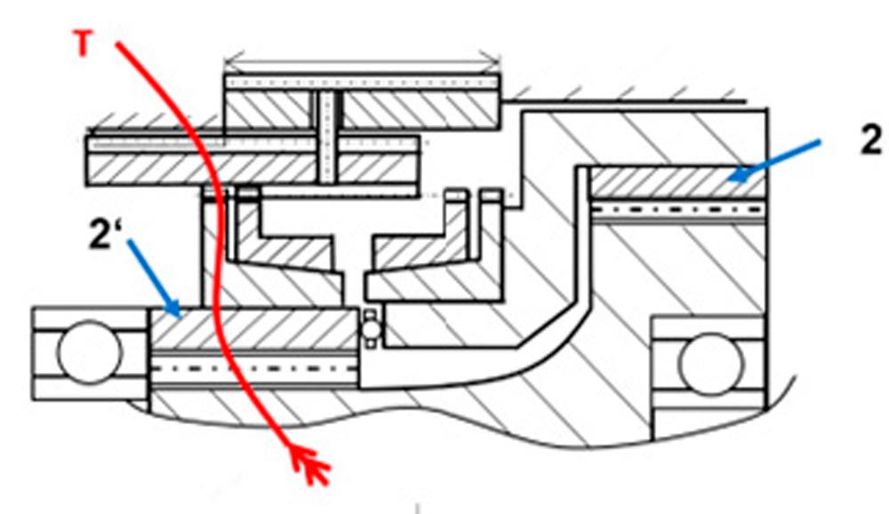
Figure 10—Starting gear (1. Gear, istart E) of the 2-speed automatic transmission.
Figure 10 illustrates the flow of torque in the first gear, characterized by the initial gear ratio istart E. The smaller ring gear is secured to the housing using a brake mechanism, which could be either a dog-clutch or a spline. The stepped planetary gears transmit torque from the first input shaft 1, which is connected to the electric motor, to the output shaft that serves as the carriers for both transmissions.
Figure 11 depicts the flow of torque during the gear shift from first to second gear. During this shifting process, the electric motor generates no torque, resulting in a net electric torque of zero. The synchronization system should possess the same maximum torque capacity (Tnmax, as shown in Figure 13) as the electric motor when operating at maximum speed. If the motor reaches this maximum speed, the customer will not experience any changes in the torque output on the output shaft. During this process, the torque required to drive the car is generated by the deceleration of the electric motor’s inertia. For the customer, the source of the torque—whether it comes from the deceleration of inertia or from electric torque—is irrelevant. The only remaining question is the duration of this time period. Initial calculations, using the inertia values of an actual electric motor, indicate that the time required for torque 0 synchronization is within acceptable limits. This implies that a hydraulic system, complete with pumps and valves typically found in a standard automatic transmission, is unnecessary. The details of this shifting process can be executed entirely through electromechanical means, as outlined in patent PCT/EP2020/079280 (not shown here) (Ref. 9).
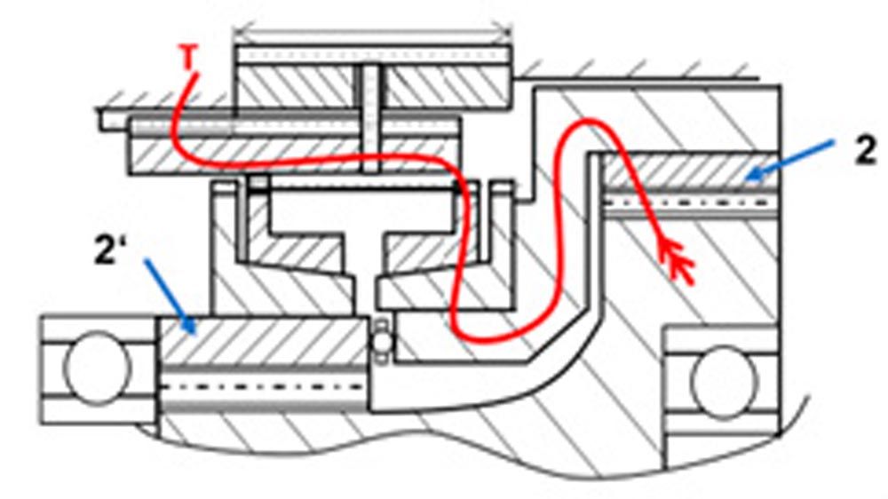
Figure 11—Torque flow while shifting process from 1 to 2 gear (starting gear to high-speed gear).
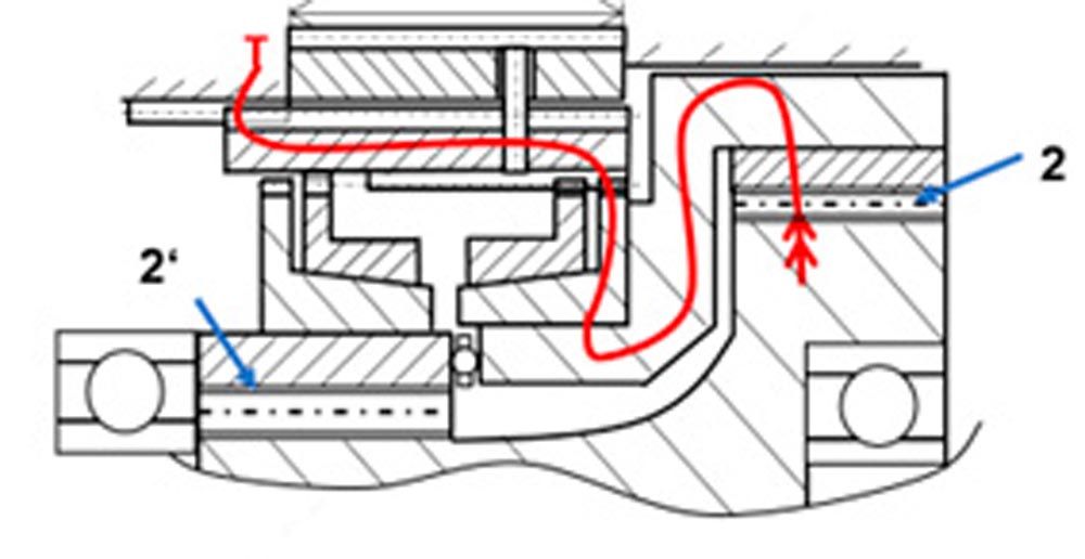
Figure 12—Torque flow in 2 gear (high-speed gear, iHE).
Figure 12 shows the torque flow in the 2 gear (the highspeed gear, iHE), here the bigger ring-gear is connected to the housing, which means the ring gear 2 (see Figure 9) stands still and the torque/power will be transmitted from sun 1 with only one planet (the bigger one of the stepped planets) to the carrier (output shaft). After the shifting process (Figure 11 and Figure 12), when no difference speed between ring gear 2 and the housing is given, you can shift the ring to the shown position, and you have the dog clutch (spline) between ring gear 2 and housing. For this position, any torque from the electric motor can be transmitted to the output shaft.
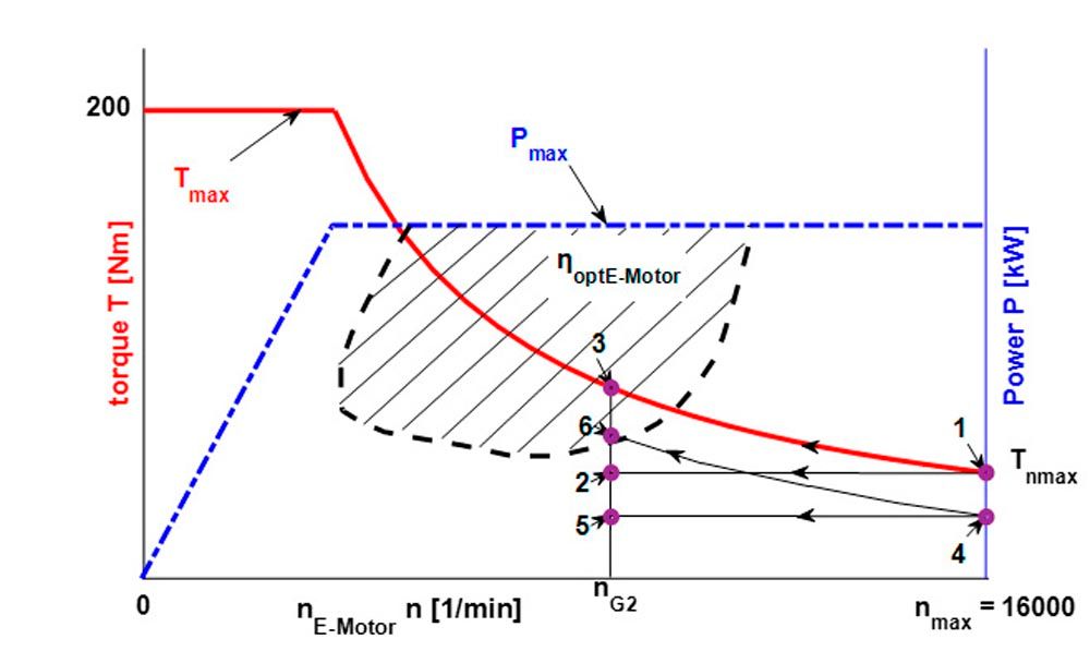
Figure 13—Shifting process for the electric motor, no torque interruption while shift from 1 to 2 gear with the synchronization (torque capacity like torque from the motor for maximum speed nmax, see Figure 1).
Shifting process 1 → 2 is proportional to the constant axial force for synchronization. In this case, the torque capacity of the synchronization has the same value as the maximum torque Tnmax of the electric motor with maximum speed nmax. For partial load—shifting 4 → 5—the axial force of the synchronization is smaller than the 1 → 2 process. In 2 or 5 no difference in the synchronization is valid and the dog clutch transmits any torque of the electric motor (Figure 12).
Conclusion
With the shown method the advantages of 2-speed automatic transmission for cars with electric motors you can calculate the ratios and the ratio-range for a 2-speed-transmission. You can make a significant improvement in the efficiency and range of the car for less electric power. The use of this 2-speed-automatic-transmission make sense for passenger cars with electric power ˂ 100 kW and for trucks (all sizes). The example illustrates a transmission that uses an electromechanical system for shifting, eliminating the need for a hydraulic system, and minimizing torque interruption. Though this example is thought for passenger cars and for trucks in general. The summary can be:
2-speed-automatic transmission are recommended for passenger cars with power ˂ 100 kW and for all trucks.

References
- Drive system technology in passenger cars. ATZ / MTZ. 3rd International ATEC Congress for Automotive Technology, Stuttgart (1991).
- “Consumption calculation taking into account various transmission efficiency maps.” Collaborative Research project 365 at the Technical University of Munich. Colloquium of the Collaborative Research project 365, Technical University of Munich (1994).
- Höhn, B.-R. “Requirements for future passenger car transmissions.” VDI reports 878, pp. 1–20. Association of German Engineers (VDI), Düsseldorf (1991).
- “Fuel savings through transmission? A systematic comparison of different types of transmisions.” VDI reports 374, p. 163f. Association of German Engineers (VDI), Düsseldorf (1980).
- https://www.zf.com/public/org/efficient and dynamic-zf.com
- https://group-media.mercedes-benz.com/marsMediaSite/en/instance/ko/Transmission-Ready-for-the-future-with-nine-gears.xhtml?oid=9904984
- Lechner G., Naunheimer H. Vehicle Transmissions, Springer Verlag 1994, 1st edition, ISBN: 3-540-57423-9.
- Pat. US 17/768.592, Hoehn GmbH. “Two-speed transmission for an electric drive system, and drive system including such a two-speed transmission.”
- Pat. PCT/EP 2020/079280, Hoehn GmbH. “2-speed-transmission for electric motors.”
- https://press.zf.com/press/de/releases/release_10181.htm
- Müller H.W. The Planetary Gears, Springer-Verlag 1998, 2nd edition, ISBN: 3 540 63227 1.
- Wirth, M. “Drag torques in synchronizations of vehicle transmissions” Dissertation 6.11.2012 TUM – FZG (phd-thesis No.: 187).
- R. Fischer, F. Kücükay, G. Jürgens, B. Pollak. The Gear Book, 2nd ed. 2016, Springer, specialist media, Wiesbaden GmbH; ISBN: 13-9783658131043.
- K. Reif. Conventional Powertrain and Hybrid Drives, Vieweg-Teubner, Bosch; ISBN: 978 3 8348-1309-9.
- P. Hofmann. Hybrid Vehicles, Springer Verlag, 2011; ISBN: 13 9783211891919.






 (14)
(14)
 (15)
(15)


