When electric drives are used in vehicles, the masking effect of an internal combustion engine disappears, allowing the noise behavior of the transmission to take center stage. At the same time, peak power and torque increase, engine speeds increase, and power must be transferred optimally in both directions due to the regenerative braking system. Conventional design parameters remain important, however: The build space is limited, durability must not be compromised, and the product must still be cost-efficient. Optical metrology as part of a hybrid measurement concept helps to overcome all these challenges.
In the automotive industry in particular, the demands placed on transmissions and thus also on gears have changed dramatically. When electric motors are used with increasing frequency, the design criteria and requirements for gear and transmission designs change. This applies to both hybrid drive concepts and pure-electric vehicles—in fact, the choice of energy source (battery or fuel cell, for example) hardly plays any role at all for the transmission. In addition to production machines, such developments call for even more precise, modern metrology.
The first question that is frequently asked is how accurate a measurement must be. A highly accurate measurement is often relatively slow—and thus expensive—putting it in direct conflict with modern gear measurement systems, with their fast cycle times on the shop floor and high-cost pressure. At the same time, today’s evaluations, such as those used for noise analysis, require an extended measurement scope compared to conventional gear measurement. It is therefore important to know exactly what needs to be measured, and what the measuring equipment needs to be capable of doing. The capability of the measuring equipment is one of the factors that determines whether the end result is a capable process.
To evaluate the capability of measuring equipment, two things are required: a target value in the form of a tolerance and a method to verify whether this tolerance can be reliably measured. The first reference for tolerances (cylindrical gears) is DIN ISO 1328, where formulas for geometry- and type-dependent tolerances for different quality classes can be found. Typical quality classes in the automotive sector range from Class 4 to Class 6 with corresponding values for numerous deviation types in the one- to two-digit-micrometer range. The method usually chosen is a capability analysis or measurement system analysis (Type 1 study), in which the repeatability (standard deviation or Cg value) and the systematic deviation (Cgk value) are determined on a certified artifact over a study range of at least 25 (typically 50) measurements. The Cg value for such an analysis is defined as follows:
where T is the drawing tolerance (as specified in DIN ISO 1328) and dt is a tolerance factor (typically 0.2, corresponding to 20 percent). si is a sigma interval factor that defines the permissible process variation via the number of standard deviations: Typically, this is 4 σ or 6 σ, ≈ 95 percent or ≈ 99 percent, respectively. Cgk is broadly equivalent to Cg but is extended to include an average deviation from a reference value. It is defined as follows:
where x is the mean value of the measurements and xm is the target value of the certified artifact. Such an artifact, sometimes called a master component A frequently selected target variable to describe a reliable process is Cg => 1.33 and Cgk => 1.33. The standard deviation (sigma, σ) used in both formulas is defined by:
where n is the number of measurements, i an index, xi a measured value at point i i, and x_ is the mean value of all n measurements.
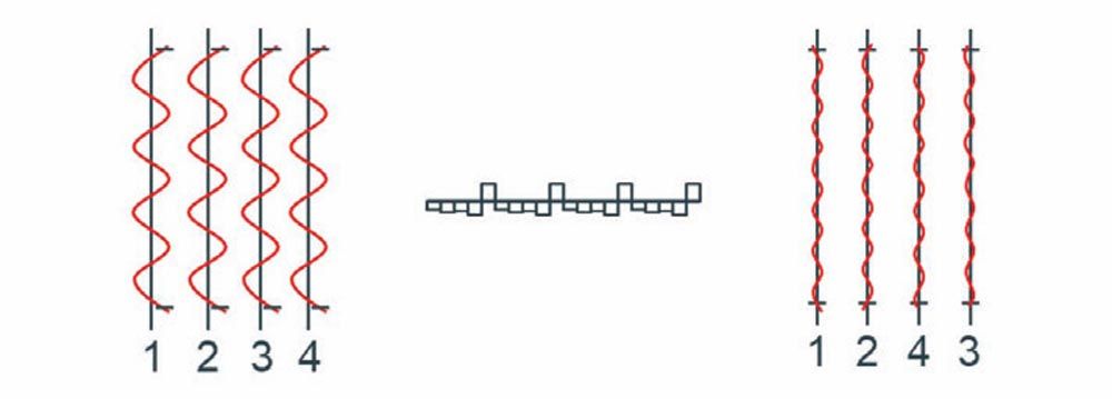
In the practice of gear measuring technology and quality control, gear designers like to modify the recommendations of DIN ISO 1328. In quality control as well, the target values for Cg and Cgk are often compared against concrete values, as are the sigma intervals and the tolerance factors. To define the demands on modern measuring equipment more precisely, it is helpful to take a look at the typical problem sources of gear noise caused by gears (see Figure 1).
Figure 1—The three typical noise sources of a transmission caused by gears (from bottom to top): uniform profile deviations, uniform single pitch deviations, and nonuniform profile deviations distributed periodically over all teeth (here on four different teeth).
Uniform profile deviations originate, for example, from the tool or are remnants of feed marks from the preliminary process. They are equally distributed on all teeth and are reflected in the tooth mesh frequencies as well as their multiples. Often, these amplitudes are in the 0.8 μm to 3 μm range. Theoretically, these defects can be detected by measuring a profile line of a tooth. In practice, three or four profile lines are often measured on different teeth. Thus, these defects can usually be determined with sufficient accuracy.
These defects are responsible for low frequencies (3rd to 8th order), and the amplitudes are in the range of 0.4 μm to 3 μm. They originate, for example, from inaccuracies of the tool or processing machine, or from inadequate mounting of tools and blanks, or they are caused when machines are started up. A pitch measurement requires measuring all teeth on the pitch measuring circle at one or more depths. To correctly determine the amplitudes of the defect, it is necessary to correctly determine the axis position of the component in addition to ensuring that the measuring equipment is accurate.
These defects vary from tooth to tooth but occur periodically over the entire periphery. Their amplitudes are in the 0.02 μm to 0.8 μm range and are responsible for what’s referred to as ghost frequencies, or ghost orders, in the evaluation. Causes for this type of deviation include the stability of the tool used in production as well as dynamic effects during production, such as vibrations, etc. In order to reliably detect nonuniform profile deviations and analyze their effects on gear noise, as many teeth as possible must be measured—and ideally all teeth. This task is usually very time-consuming with conventional tactile metrology.
The minimum requirements (3 μm amplitude at 20 percent and a 4-σ interval) of a piece of measuring equipment to reliably measure the described deviations can be determined by converting and plugging into formula 1. The limiting value of a standard deviation that can still be toleranced is obtained in this way (σ ≈ 112 nm). Such a value can be achieved for modern tactile precision measuring centers, but the measurement reliability is minimal even when the amplitude is reduced by half to 1.5 μm (σ ≈ 56 nm). The same threshold value must apply for fast, optical systems. However, due to the higher number of measurements within the same time frame, it is recommended to increase the study size. In critical cases, Klingelnberg works with a minimum of 100 measurements to ensure that the results obtained remain stable over the duration of an entire shift (typically seven to eight hours).
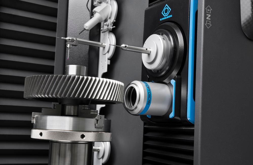
Uniform deviations—both in profile and pitch measurements—can currently be determined quickly and with sufficient process reliability using hybrid precision measuring centers. The profile lines are measured using the tactile method and the pitch by means of optical sensors. Both systems achieve sufficient accuracies even under production conditions. Complete integration of optical metrology as a hybrid measuring concept in the precision measuring center means that the fast, contactless metrology benefits from flexible, tactile measurement of the workpiece axis, temperature compensation, and vibration isolation as an optional feature. Nonuniform profile defects currently require a comparatively high measurement effort. The required measurement precision in the form of a standard deviation of σ<<100 nm to reliably detect corresponding defect patterns can often only be achieved with tactile metrology and measurement strategies optimized for speed. Due to the nonuniformity and low amplitudes, deviations of this type are the greater challenge for gear measuring technology.
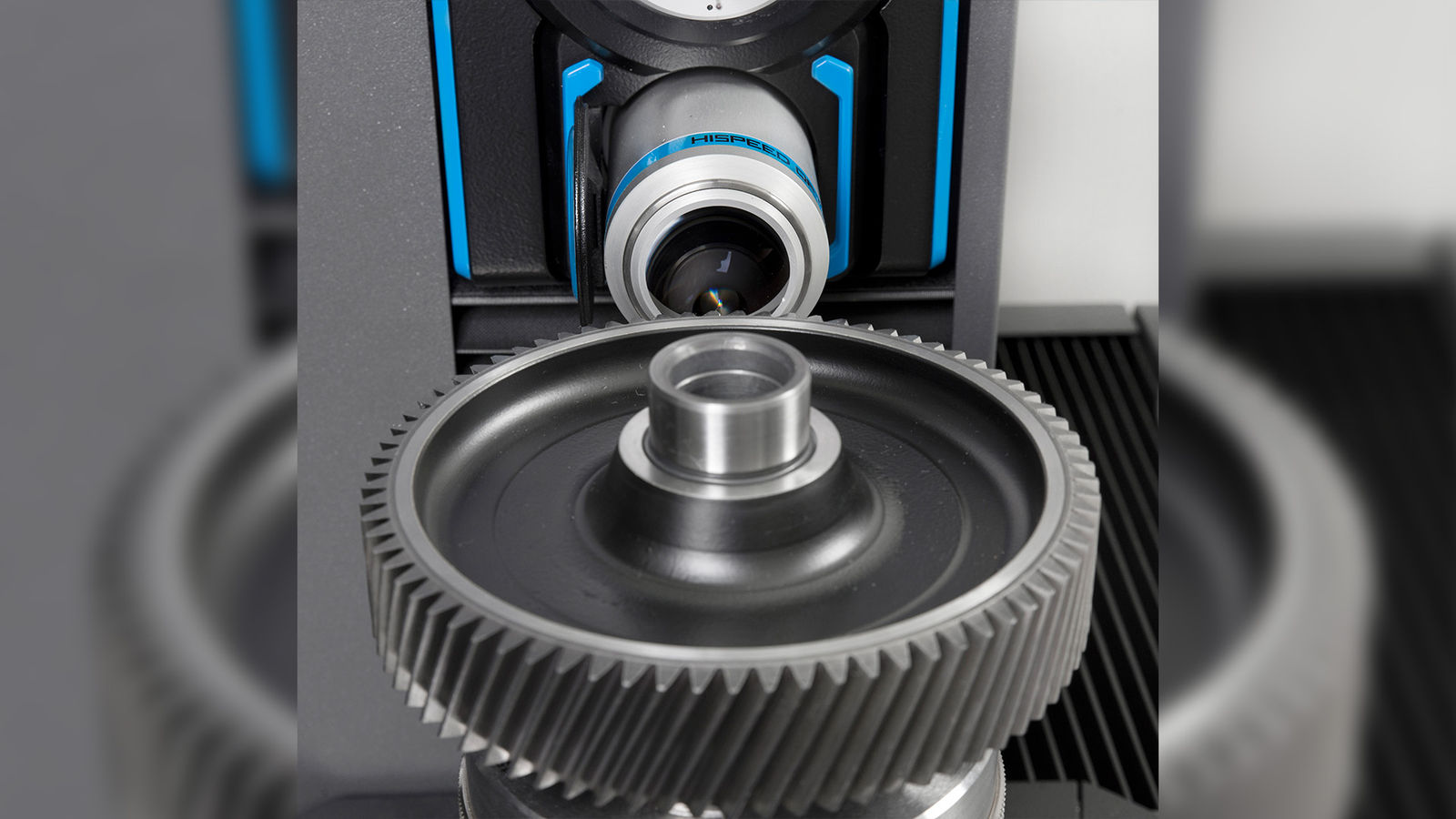
As shown in the example described here, for modern gear measuring tasks, a measuring system benefits from increased speeds—but this must not be at the expense of accuracy. The Klingelnberg optical system was developed and produced largely in-house and optimized for maximum accuracy right from the start. Optical pitch measurement has been achieving consistently reproducible results since the first delivery in 2021 and is thus the first step towards solving current challenges with modern metrology and conventional accuracy (see Figure 2).
Figure 2—Hybrid metrology on a final drive for electromobility, gear quality 4 according to DIN ISO 1328, 82 teeth.
Following the same approach, the next steps will solve the most time-consuming tasks at higher speed but with the measurement precision customers are accustomed to. Here, Klingelnberg is focusing on the challenges that the industry is currently facing, with an emphasis on integrated measuring concepts that can be further developed, particularly intelligent evaluation strategies.
With its optical metrology, Klingelnberg is keeping pace with changes in the industry and delivering the usual quality and flexibility that are required for higher gear throughput while also satisfying the requirements for state-of-the-art evaluation methods (Gear Deviation Analysis, GDA) and interfaces such as OPC UA (Unified Architecture Open Platform Communications). Hybrid metrology can be combined particularly effectively with the highspeed Höfler R 300 Cylindrical Gear Roll Testing Machine, a reliable combination for noise and quality control on the networked shop floor.