Sequential machining on single-purpose machines has so far led to a long process chain with a long throughput time. The manufacturing processes commonly used to date for internal gears, such as gear shaping or gear broaching, offer only limited possibilities for economically viable hard-finishing processes, which is why the gearing was previously finished before heat treatment. Due to the lack of a hard finishing process, there was no possibility of compensating for the changes in volume, shape, and position of the gearing induced by the heat treatment. In addition, these geometry changes are very difficult or even impossible to predict due to the large number of influencing factors, making stable prediction extremely difficult. Due to the lack of a hard finishing process, the process chain described was quality-critical and the manufacturing process was not stable.
Due to today’s customer and market requirements, continuous process improvements in terms of costs, throughput time, and quality are essential. In the example considered here, the implementation of gear skiving and the associated process integration on a universal machining center made it possible to significantly reduce the process chain and throughput time. By adapting the process characteristics, e.g., to small chip thicknesses and the use of high-performance cutting materials and coatings, it is also possible to carry out hard finishing after heat treatment using gear skiving (Ref. 3). This can sustainably improve component quality. The optimized combined integrative process chain on universal machining centers is shown as an example in Figure 5.
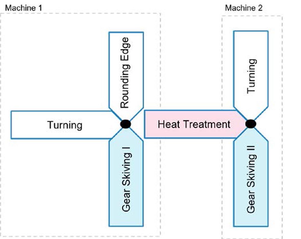
Figure 5—Combined integrated process chain on a universal processing machine.
The tool and process design is crucial for a stable gear skiving process. Due to the complex engagement conditions during gear skiving, which change throughout the process, a deep understanding of the process and high-quality calculation and simulation tools are the basis for a stable process, good component quality, and low tool wear (Refs. 1, 2, 3, 13, 15). In the application considered here, a gear skiving tool was designed for premachining in the soft state and for hard fine machining in the hard state (Ref. 16).
A centric process with a conical tool as shown in Figure 2 is used. The tool data is summarized in Table 2.
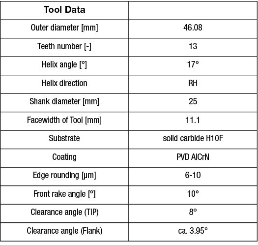
Table 2—Tool data.
Setup
The components are manufactured on a DMG CTX beta 1250 TC universal machining center with main and counter spindles. The GearSkiving 2.0 gear skiving cycle from DMG is used for process control (Refs. 10, 11). The workpiece is clamped in a collet for gear skiving on the main spindle on the bearing seat previously machined on the counter spindle. Figure 6 shows the tool and the workpiece in the processing machine.
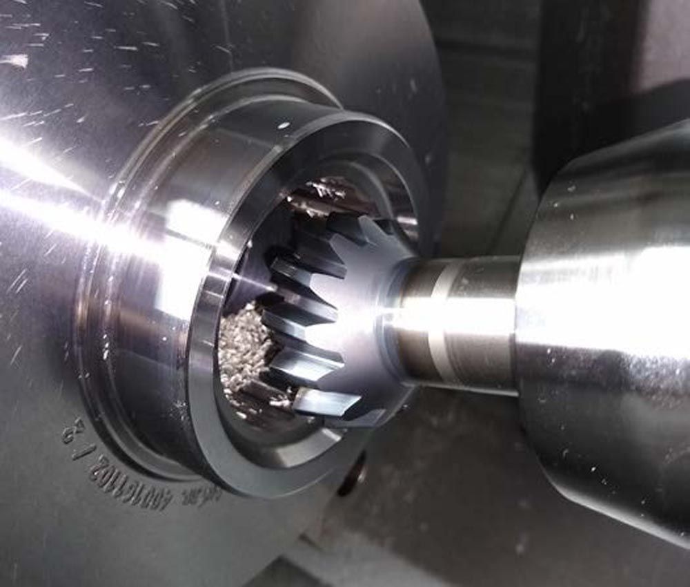
Figure 6—Skiving tool in use.
Premachining
During premachining, the root circle is finished with the narrow tool in the direction of the upper root circle dimension without protuberance. The allowance provided in the tool is approx. 0.1 mm/flank. The cutting values summarized in Table 3 are used.

Table 3—Cutting data, semifinishing.
Machining is performed with a degressive infeed strategy in seven cuts, whereby the cutting values for semifinishing and finishing are adjusted in the last two cuts. The following figure shows the infeed strategy for semifinishing, Figure 7.
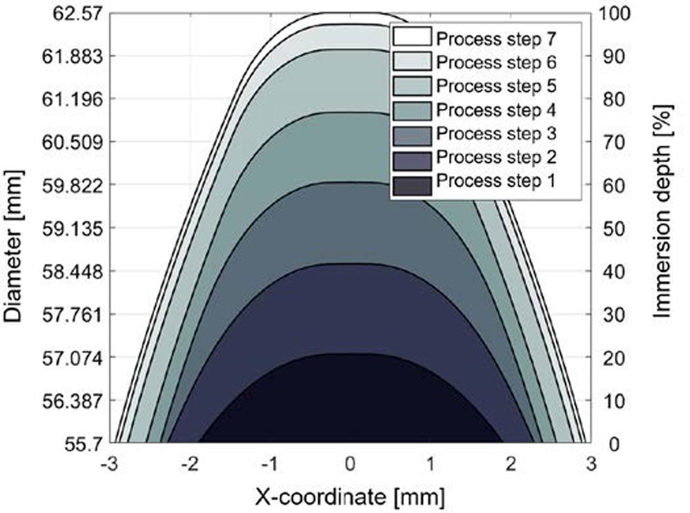
Figure 7—Premachining infeed strategy, OpenSkiving result graphic (Ref. 13).
Finishing After Heat Treatment
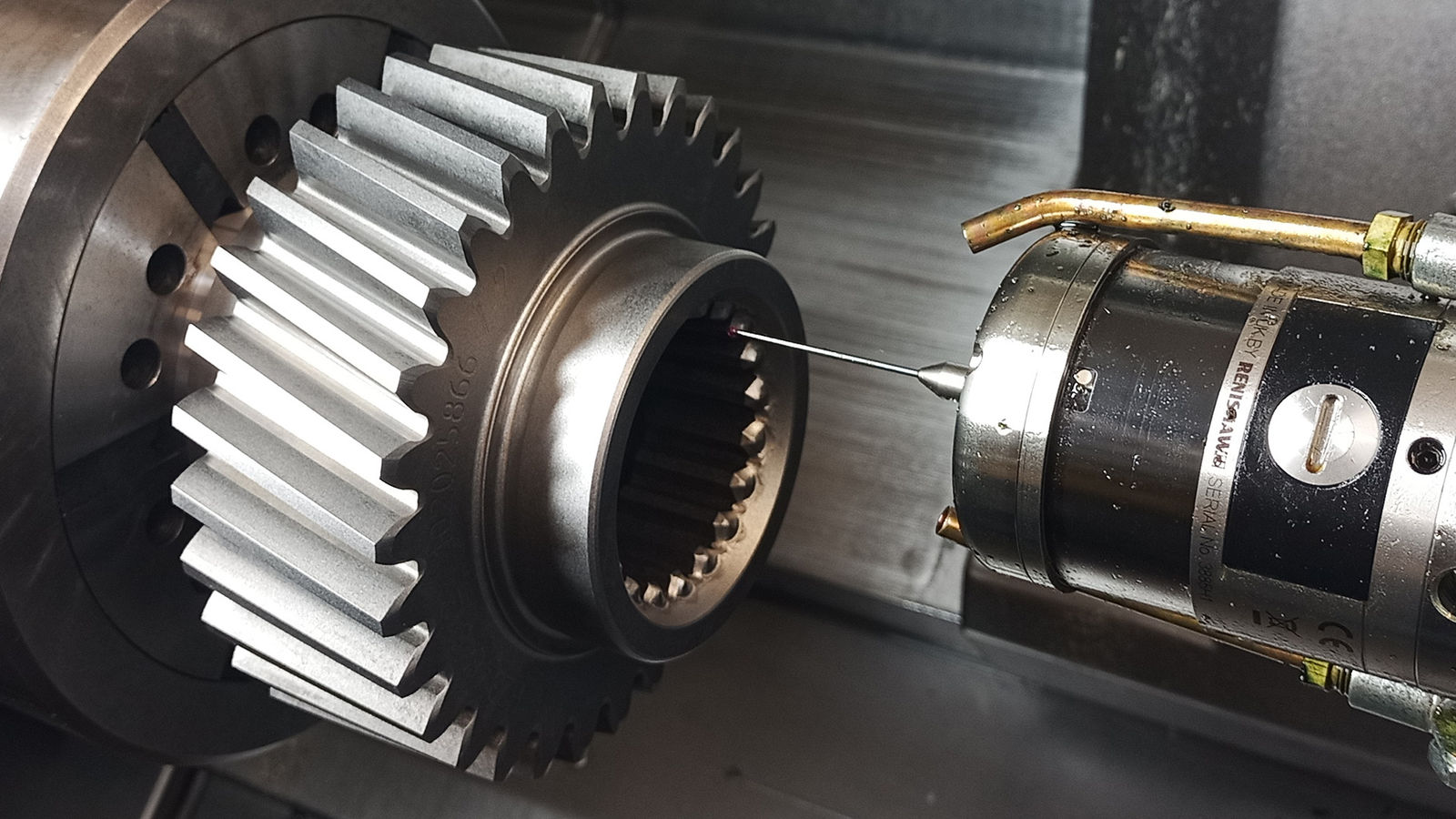
After heat treatment, machining takes place in the same setup as during premachining. Due to the existing tooth gaps in the workpiece, determining the tooth gap position is crucial for machining after heat treatment. For this purpose, a macro was implemented on the universal processing machine which determines the angular position of the tooth gap using a measuring probe. Figure 8 shows the determination of the tooth gap position on the processing machine and the tool cutting edge centered in the tooth gap.
In addition to the angular position of the tooth space on the workpiece, the exact angular position of the cutting edge must also be determined. Deviations in the angular positions of the tool and workpiece lead to incorrect effective positions in the process, resulting in deviations in the tooth profile and changing the meshing conditions.
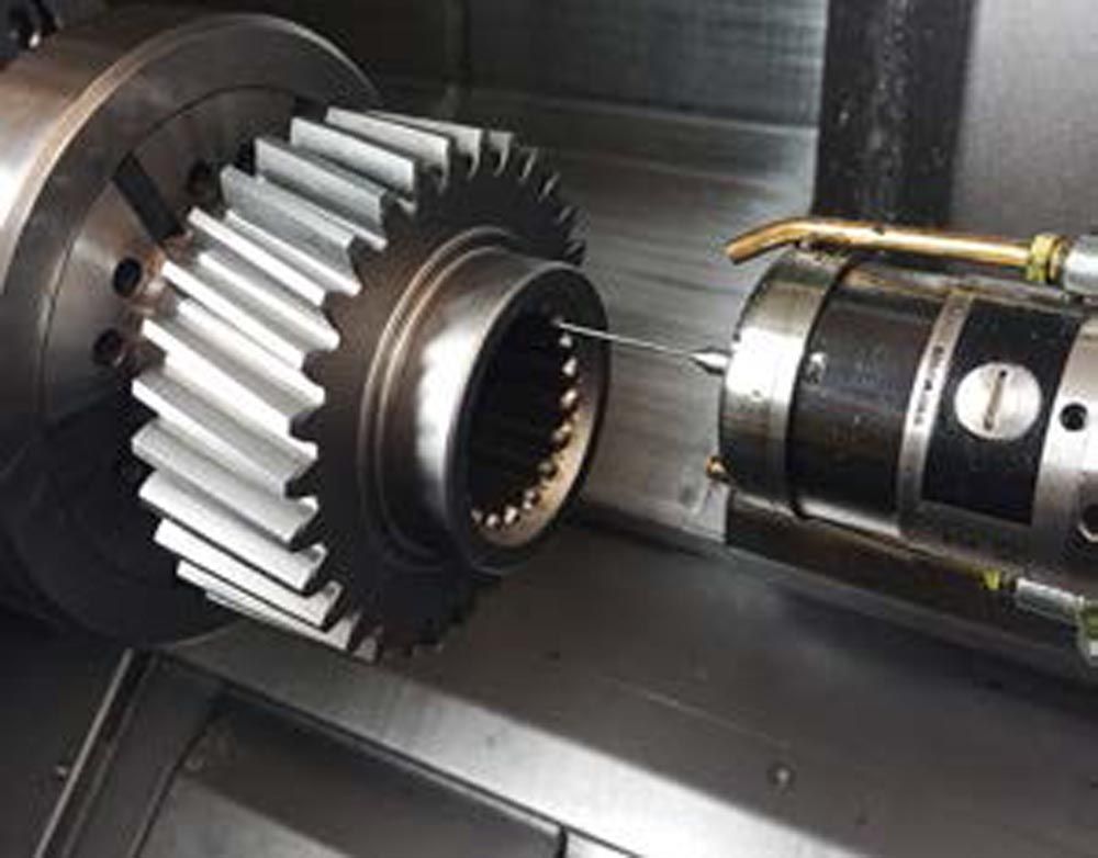
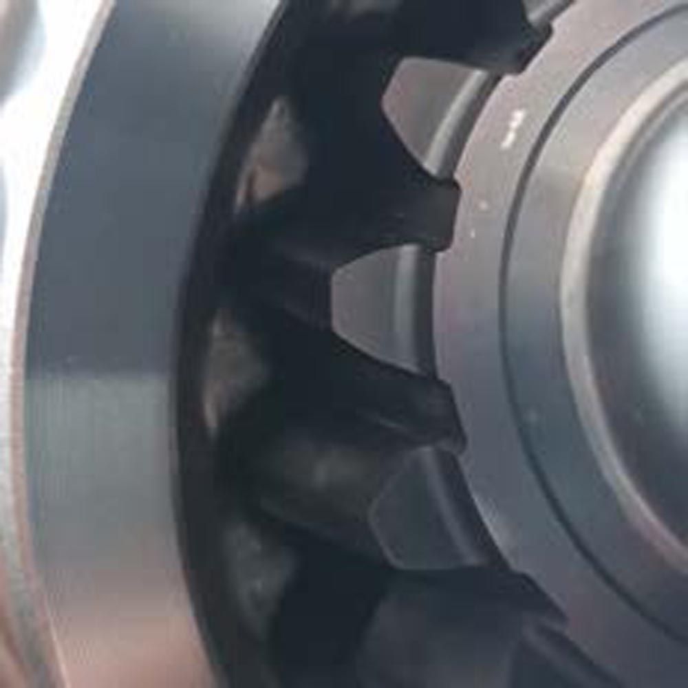
Figure 8—Indexing on the processing machine and tool in the engaged position.
Hard machining is carried out in a single flank cut in the application to reduce the tool load. The infeed is performed rotationally via the pendulum angle { separately for the right and left tooth flank. This reduces the tool load and both tooth flanks can be corrected and modified independently. Machining is carried out with the theoretical machining parameters summarized in Table 4. Due to the changes in shape, position, and volume induced by the heat treatment and inaccuracies in determining the angular position, the actual infeed in the process can vary in the first cut.

Table 4—Cutting data, hard-fine-machining.
The used processing principle is outlined in Figure 9.
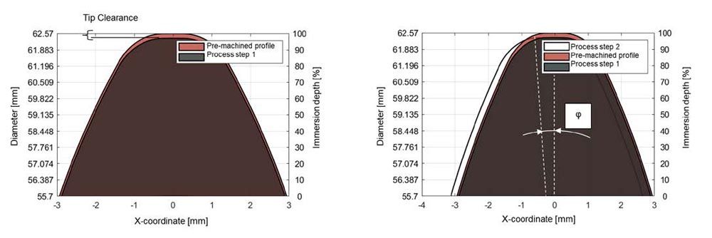
Figure 9—Processing principle hard skiving, OpenSkiving result graphic (Ref. 13).
In hard fine machining, it is advisable to design the process parameters in such a way that the resulting chip thickness is low to reduce the load on the tool’s cutting edge. The process considered here was simulated with OpenSkiving (Ref. 13) to evaluate the chip thickness, clearance, and rake angle as well as cutting arc length, etc. arising in the process. Figure 10 shows the calculated values of the maximum local chip thickness over the unwound tool cutting edge.
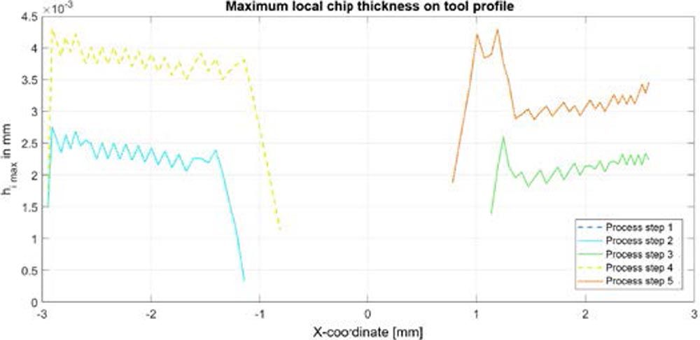
Figure 10—Maximum local chip thickness on the unwound tool profile, OpenSkiving result graphic (Ref. 13).
The analysis shows that the process according to Table 4 produces very low local chip thicknesses along the tool cutting edges. These small chip thicknesses lead to a low tool load, which is beneficial for hard machining. Single flank machining reduces the contact length of the tool’s cutting edges. It is also seen, that the tool tip area with the theoretically expected maximum chip thickness is left out (Refs. 1, 2). This has a positive effect on tool wear and machining quality.
The chip thickness is influenced by the axial feed, among other things. When adjusting the axial feed, a compromise must be found between tool load, envelope cut deviation in the flank direction, and machining time to meet the requirements for hard machining.
During the implementation of the hard skiving process, profile angle deviations were observed on the right tooth profile, the outgoing flank, Figure 11. These profile angle deviations are partly due to the different meshing conditions on the incoming and outgoing flanks. The profile angle deviation can be corrected by correcting the relative position of the tool to the workpiece. Here, the position and axis cross angles are the control variables. In the application considered here, the profile angle error fHa on the right tooth flank could be corrected by adjusting the axis cross angle ∑. For the correction of such deviations, a deeper understanding of the process and the support of calculation models for process simulation is necessary (Refs. 13, 15). Figure12 shows the corrected result after adjusting the process control.
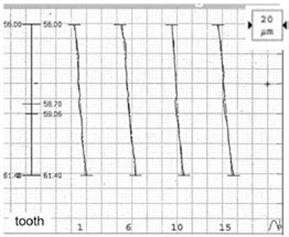
Figure 11—Profile angle error before correction.
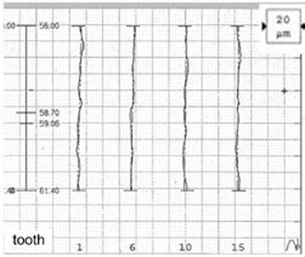
Figure 12—Corrected profile.
Figure 13 summarizes the final results after process optimization. In addition to the evaluation according to DIN 5480 (Refs. 8, 9), the gearing was also evaluated according to DIN 3962-1 to DIN 3962-3 (Refs. 5, 6, 7) in order to be able to evaluate the quality achieved in relation to this standard. The gearing qualities reliably achieved in the hard skiving application are summarized in Figure 13.
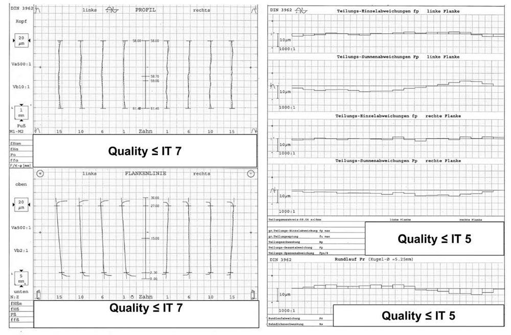
Figure 13—Final result hard hard-skived internal spline.
Result and Summary
By changing the process from sequential processing on single-purpose machines to combined processing on universal processing machines, the process chain and therefore the throughput time could be reduced by three weeks. The use of new cutting materials and technologies has also drastically reduced the machining costs of internal spline by 30–50 percent. Furthermore, the newly introduced hard-finishing process increases component quality and significantly reduces quality costs. In the example presented here, process integration, process analysis, and optimization made it possible to introduce process-reliable hard fine machining with skiving up to a quality of IT 7.
The right process design is always a balancing act between cost-effectiveness, quality, and process stability. Here, gear skiving offers a wide range of control variables that must be coordinated on a case-by-case basis.
Practical implementation in production shows that a cross-functional understanding of the process by all parties involved in the process is essential for the successful implementation of gear skiving technology (Ref. 15).
References
- Bauer, R. “Modellbasierte Auslegung von Mehrschnittstrategien beim Wälzschälen,” Dissertation, Chemnitz, 2018.
- Bechle, A. “Beitrag zur prozesssicheren Bearbeitung beim Hochleistungsfertigungsverfahren Wälzschälen,” Dissertation, Karlsruhe, 2006.
- Bertsch, D. “Optimierung der Werkzeug- u. Prozessauslegung für das Wälzschälen von Innenverzahnung,” Dissertation, Karlsruhe, 2017.
- Briel, M. “Power Skiving for Gears: Advanced Solutions and Contributions”, Gear Solutions, April 2024, pp. 34–37.
- Deutsches Institut für Normung e.V. (1978), “Toleranzen für Stirnradverzahnungen: Toleranzen für Abweichungen einzelner Bestimmungsgrößen,” DIN 3962-1 (1978.08), Berlin: Beuth Verlag GmbH.
- Deutsches Institut für Normung e.V. (1978), “Toleranzen für Stirnradverzahnungen: Toleranzen für Flankenlinienabweichungen,” DIN 3962-2 (1978.08), Berlin: Beuth Verlag GmbH.
- Deutsches Institut für Normung e.V. (1978), “Toleranzen für Stirnradverzahnungen: Toleranzen für Teilungs-Spannenabweichung,” DIN 3962-3 (1978.08), Berlin: Beuth Verlag GmbH.
- Deutsches Institut für Normung e.V. (2006), “Passverzahnungen mit Evolventenflanken u. Bezugsdurchmesser—Teil 1: Grundlagen,” DIN 5480-1 (2006.03), Berlin: Beuth Verlag GmbH.
- Deutsches Institut für Normung e.V. (2006), “Passverzahnungen mit Evolventenflanken u. Bezugsdurchmesser—Teil 2: Nennmaße und Prüfmaße,” DIN 5480-2 (2006.03), Berlin: Beuth Verlag GmbH.
- DMG MORI, “CTX beta 1250 tc 4a”, 2023-04-23, https://de.dmgmori.com/produkte/maschinen/drehen/drehfraesen/ctx-tc/ctx-beta-1250-tc-4a
- DMG MORI, “GearSkiving 2.0,” 2023-04-22, https://de.dmgmori.com/produkte/digitalisierung/technologiezyklen/drehen-fraesen/zerspanen/gearskiving
- Hüsahm, A. “Modellbildung und experimentelle Untersuchung des Wälzschälprozesses,” Dissertation, Karlsruhe, 2002.
- KIT wbk Institut für Produktionstechnik “OpenSkiving,” 2024-04-23, https://openskiving.kit-campus-transfer.de/
- Klocke, F., Brecher, C., “Zahnrad- u. Getriebetechnik,” Carl Hanser Verlag München, 2017.
- Mahl, S. “Wälzschälen—Vorsicht ist besser als Nachsicht,” 5.Fachseminar Wälzschälen/Powerskiving 2023, 23. November, Deutschland.
- Sandvik Coromant, “CoroMill 178, Wälzschälwerkzeuge,” 2023-04-25, https://www.sandvik.coromant.com/de-de/tools/milling-tools/gear-milling-tools/coromill-178


