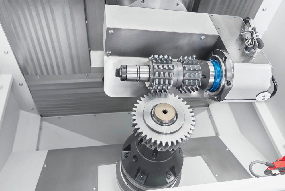
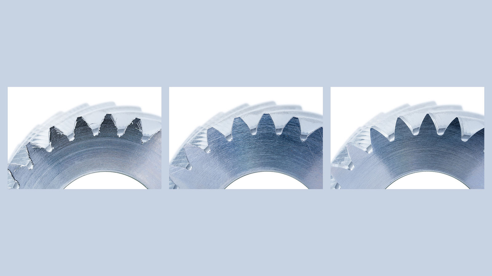
While chamfering with hobs has been known for decades, chamfer hobbing takes the process to a new level. Chamfering is performed using a Gleason chamfer hob. The cutting tool has characteristics very similar to a gear hob. It is made with high-speed steel and features AlCroNite Pro coating for exceptional tool life in dry-cutting conditions. With Gleason chamfer hobbing, one chamfer hob is used for each tooth flank, with a tooth profile specifically designed for the chamfer form that’s required. The chamfer hob looks like a standard gear hob but with asymmetric teeth. One flank is designed for cutting the chamfer, the other flank is designed not to touch the counter flank. This process delivers great flexibility regarding required chamfer angles. Typically, parallel-chamfer forms are cut along the tooth edge only or including the root area. Chamfer angles like those commonly produced in the chamfer rolling process are targeted (15–30 degrees on the obtuse edge, 25–35 degrees on the acute edge). In the chamfer hob design process, Gleason technology software is used to simulate the required chamfer and identify and avoid all potential collisions of the tools with the counter flank and interfering contours above and below the actual gearing. By cutting into the gap, burrs are avoided on the face side of the gears. With typical chamfer angles, there are no measurable burrs on the flank that require removal downstream. These factors, plus tool shifting to more evenly distribute wear and extend tool life, result in the absolute lowest tool-cost-per-piece: just one cent or less on average for a typical EV intermediate gear.

Chamfer hobbing with low tool cost.
Fly Cutter Chamfering
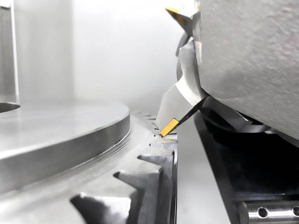
While fly cutter chamfering has long been used in bevel gear cutting applications, it has just recently been made available for larger (truck-size) cylindrical gear production and those applications where maximum flexibility and frequent part changeover make the use of dedicated tools (e.g., chamfer rolling and chamfer hobbing) prohibitively costly. Instead, this process mills the chamfer with its desired characteristics along the gear edge contour by synchronizing a fly cutter—generally a star-shaped body with four standard, replaceable inserts—with workpiece rotation. Since each edge of the tooth is done separately and the chamfer size and angle depend on machine movements, not tool design, the process is quite universal. With just a relatively few different standard inserted blade sets and base bodies, a single tool can be used for different modules, pressure angles and number of teeth. Size and chamfer angle can easily be programmed.

Fly cutter chamfering for the highest flexibility—one tool for many different workpieces.
Chamfering Integration Made Easy
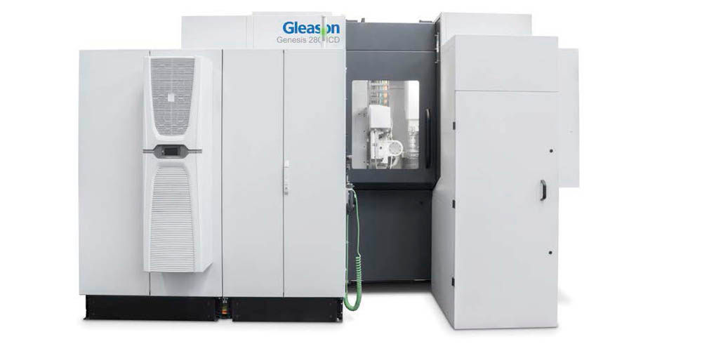
Naturally, all the aforementioned chamfering processes must be made available to gear manufacturers such that their impact on cycle times, tool cost per piece and the price of total ownership is so small as to be virtually inconsequential. Chamfering can be fully integrated with hobbing and power skiving machines and performed in parallel with these primary cutting processes. In cases where hobbing machines already exist and replacement is not desirable, chamfer design requirements can, of course, be met with standalone chamfering machines such as the Gleason 280CD, which currently offers both chamfer hobbing and fly cutter chamfering. In every case, the approach has always been to make chamfering technologies as readily available and as easy to integrate as the cutting processes themselves. For example, for the latest requirements of EV transmission gears, pinions, and shafts, where cycle times and tool cost per piece are critically important, Gleason offers the new horizontal 100HCD hobbing machine. It performs radial chamfering in parallel with gear hobbing, thus not impacting chip-to-chip times. The new vertical Genesis 180HCD and 280HCD hobbing machines also feature chamfering in parallel with gear hobbing: chamfer hobbing on the 180HCD and the option for both chamfer hobbing and fly cutter chamfering on the 280HCD for workpieces with diameters up to 280 mm and module 5 mm. Note that these machines feature either an additional gantry loader or a 4-station ring loader to link gear hobbing with chamfer cutting and external automation/storage.

Gleason Genesis 280HCD hobbing machine with integrated chamfer station for chamfer hobbing or fly cutter chamfering.
Finally, when any of these technologies cuts a chamfer, the quality engineer must ensure it’s in tolerance according to the part print. Measuring is mandatory. This process can be slow and laborious with conventional mechanical contour measurement machines. Today’s gear inspection technologies, like the Gleason GMS series of analytical gear measuring systems, can be equipped with integrated chamfer inspection software to speed and simplify the chamfer inspection process by providing a complete analysis of different chamfer sizes and angles, thus simplifying comparison with the workpiece drawing.
Summary
These latest solutions are available today to apply the right chamfer process to widely disparate applications such as automotive-type gears and shafts, truck-size gears, or job shop applications. Most importantly, the total ownership cost for chamfering has never been lower, nor has the case for chamfering been more compelling.
gleason.com


