Bevel Gears

Free Gear Technology Subscriptions
Free Gear Technology Subscriptions
FEATURED VIDEO
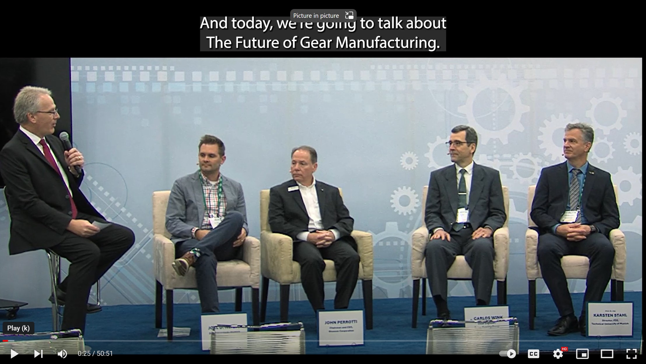
January 10, 2024
RECOMMENDED
-
Step Right Up! It’s Time to Preview IMTS 2024
August 15, 2024
-
Combi Honing of Gears
August 15, 2024
-
IMTS 2024 Will Be Here Before We Know It
July 23, 2024
-

-
Mission to Mars
August 15, 2024
-
-
Mission to Mars
August 15, 2024 -
Step Right Up! It’s Time to Preview IMTS 2024
August 15, 2024