[advertisement]
Feature Articles

June 20, 2023

Sanjay Gupta


Hobs Hobbing Features

Corrected Lead Hobs

Understanding their use cases and machine settings

During our interactions with customers, we find the common challenge faced by customers about getting incorrect component parameters using corrected lead hobs.

To address the challenge, we will talk about what corrected lead hobs are, why it is necessary to design such hobs, and how to set up the hob on the machine depending upon the type of hobbing machine (manual, semiautomatic CNC, or CNC).

What Is a Corrected Lead Hob

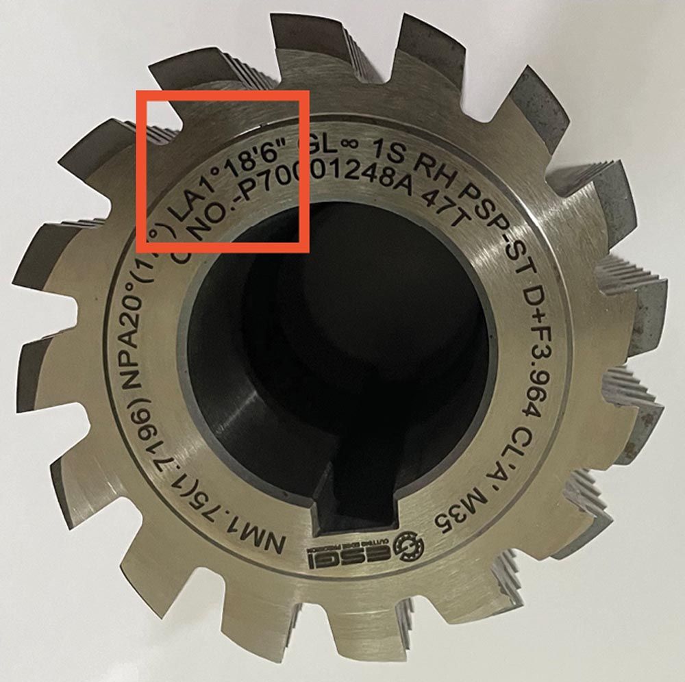
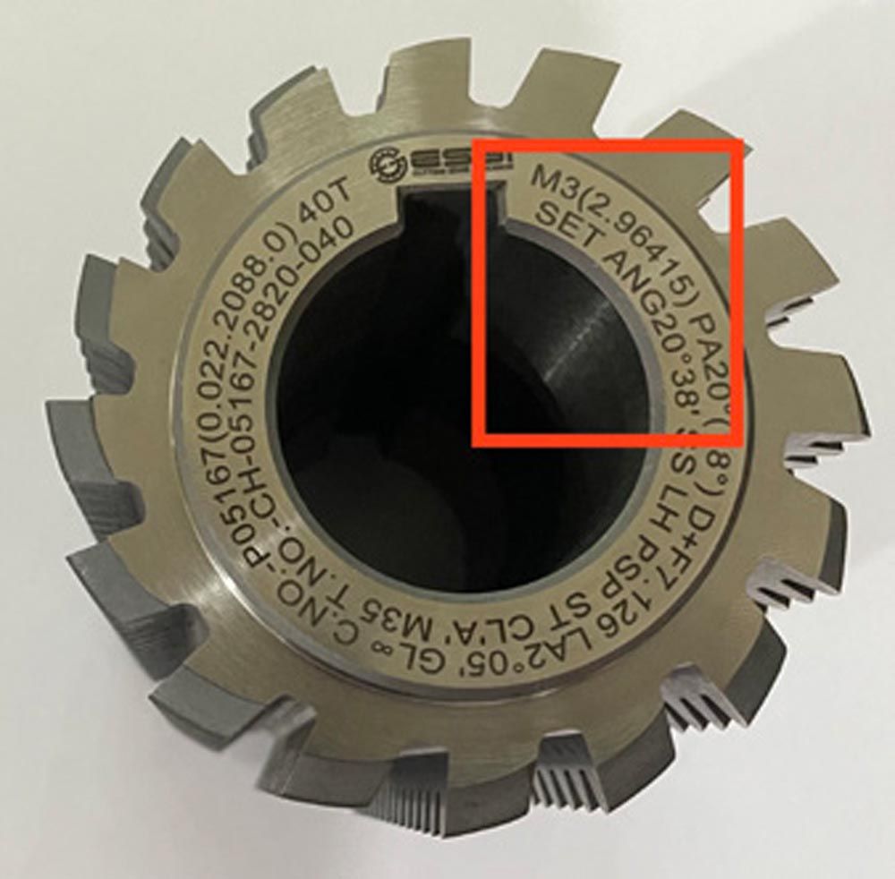
The module and pressure angle of corrected lead hobs are different from the module and pressure angle of the component. If the pressure angle of a hob is less than that of the component, then it is a short lead hob and if the pressure angle is greater, then it is a long lead hob.

Why It Is Necessary to Design Corrected Lead Hobs

When the true involute form (TIF) diameter and fillet radius of a component is not achieved with a standard design, then the pressure angle of the hob is reduced or increased to obtain the correct TIF and fillet radius of the component. This can be explained with the below example.

gt0623_Page_30_Image_0001.jpg
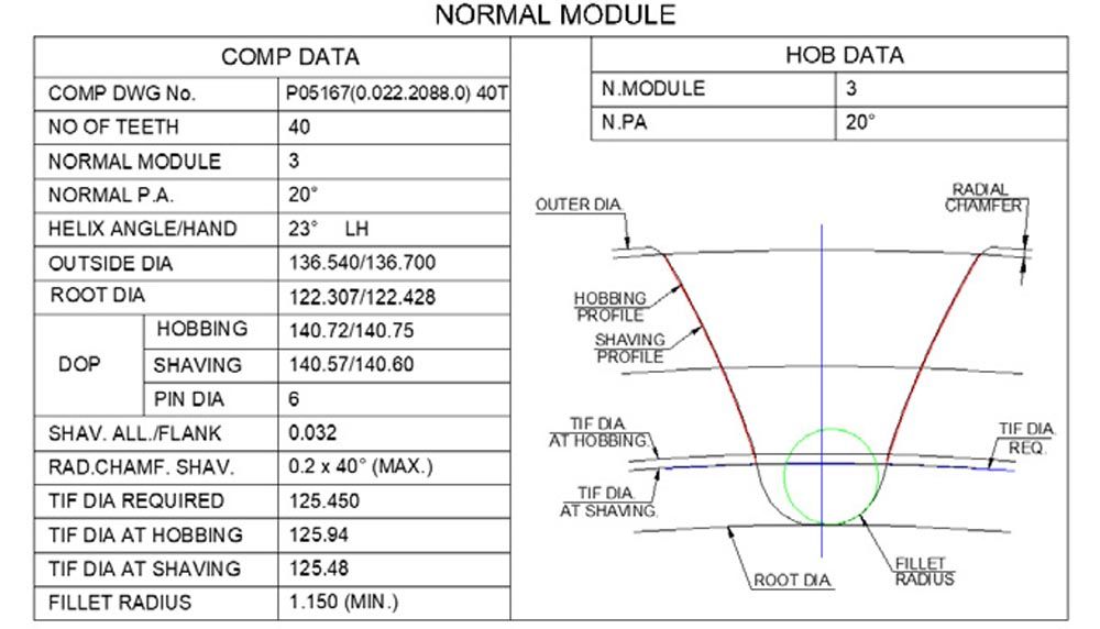
Figure 1—Component generated profile with standard design.

Standard Hob Design

Principally, TIF shaving should be below the required TIF diameter. However, when the hob is designed with the standard method, TIF required and TIF shaving are almost at the same values. Please refer to the component generated profile in Figure 1.

gt0623_Page_30_Image_0002.jpg
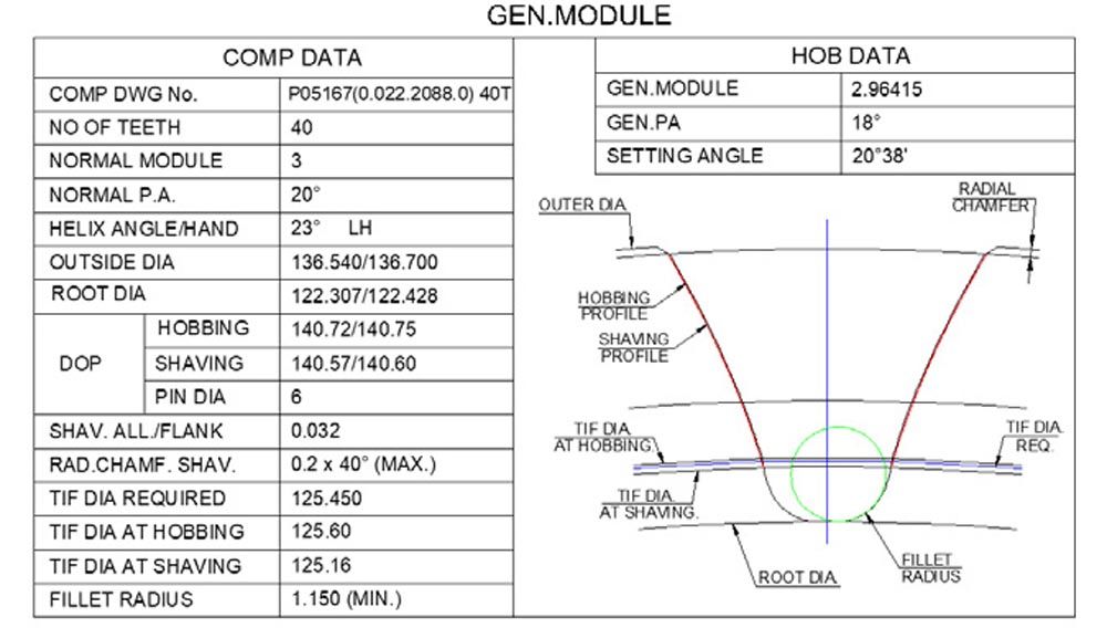
Figure 2—Component generated profile with corrected design.

Corrected Lead Hob Design

To achieve the principal requirement of getting TIF shaving below TIF required, the pressure angle of the hob is reduced from 20 degrees to 18 degrees. Please refer to the component generated profile in Figure 2.

Share and save:


This article appeared in the June 2023 issue.


Read PDF

[advertisement]

Hence, the corrected lead hobs are necessitated to be designed due to limitations in achieving the component data.

Marking Guidelines on Hobs

Spur Gears

The lead angle is the same as the set angle. Hence, only the lead angle will be marked on the hob (Figure 3).

Helical Gears

The hob set angle is different from the hob lead angle. Though, both the lead angle and set angle are marked on the hob, only the set angle should be referred to for setting the machine (Figure 4).

gt0623_pg_31_Image_0001.jpgFigure 3—Hob marking for spur gear.
gt0623_Page_31_Image_0002.jpgFigure 4—Hob marking for helical gear.


Machine Settings

Corrected lead type designed hobs bring new challenges at the time of usage like understanding the correct machine settings depending upon the type of gear and machine, considering the wide presence of manual, semiautomatic CNC, and CNC hobbing machines.

Manual Hobbing

Spur Gear

The hob lead angle as marked on the hob is to be manually set on the machine. For example, referring to Figure 3, the value to be manually set on the machine is LA1°18'06".

Helical Gear

Hob set angle (not lead angle) as marked on the hob to be manually set on the machine. For example, referring to Figure 4, the value to be manually set on the machine is SET ANG 20°38'.

Semiautomatic-CNC Hobbing Machines (Hob lead angle set up is manual)

The procedure to set up the angle remains the same as in manual hobbing machines. However, you will find two files for inputting the data, one for component data and another for hob data.

Component Data File

Input original module and original pressure angle (Module 3 and pressure angle 20 degrees as in Figure 1).

Hob Data File

Input corrected module and corrected pressure angle (Module 2.96415 and pressure angle 18 degrees as in Figure 2).

CNC Hobbing Machines (Hob Lead Angle Is Calculated by Machine)

In this case, there is no need to input the lead angle or set angle because it is calculated by the CNC. The operator must ensure to input the values in the component and hob files.

Component Data File

[advertisement]

Input the original Module and original pressure angle (Module 3 and pressure angle 20 degrees as in Figure 1).

Hob Data File

Input the corrected module and corrected pressure angle (Module 2.96415 and pressure angle 18 degrees as in Figure 2).

However, the operator must ensure that the hob set angle calculated by the machine is the same as what is marked on the hob.

Since any mistake in machine setting and/or feeding the data will lead to incorrect component parameters, the article will help clarify the necessity to design, how to use corrected lead hobs and understand machine settings based on the type of gear and machine.

esgitools.com