Cutting Tool Selection Criteria for Cylindrical Gear Manufacturing
Introduction
This paper is divided into two parts. The first part is a general digression on the pressure angle on cylindrical gears. The pressure angle is a variable that plays an important role in defining the geometry of gears and hobs, yet it is not widely discussed. This introduction serves as a prerequisite for the second part of the paper.
The second part will show an application case of choosing the most suitable hob to cut a given gear. In this selection process, particular attention will be paid to the pressure angle of the hob for cutting with modified rolling, i.e., with a reduced pressure angle compared to that of the gear.
Part One: the pressure angle α
Definition
Typically, in gear geometry training courses, time is spent on profile shifting as an inexpensive means of adapting to the imposed center distance and to balance specific sliding. It is noted that the profile shift has effects especially on gears with few teeth.
In schooling, at least in Italy, the profile shift x is often introduced only as a means of avoiding undercutting for gears with fewer than 17 teeth. This somewhat myopic and biased view learned at school age, is difficult to remove with on-the-job training, which occurs later.
Much less time is devoted to the in-depth study of the pressure angle mainly because any modification, a value different from the standard ones (fixed at 20 by dogma), requires the purchase of specific tools despite the fact that the pressure angle affects bending strength, tooth thickness at the tip diameter and contact ratio (noise reduction)(Ref. 1).
Therefore, it tends to be taught that the profile shift and the pressure angle have similar effects on the tooth shape, but intervening on the former is cost-free, while modifying the latter is expensive (Ref. 1).
Often overlooked is the possibility of cutting gears with tools that have different pressure angles from the gear, resulting in benefits on several fronts. These type of tools are called “corrected lead” (Ref. 2), “short-pitched” (Ref. 3) or “modified rolling” hobs.
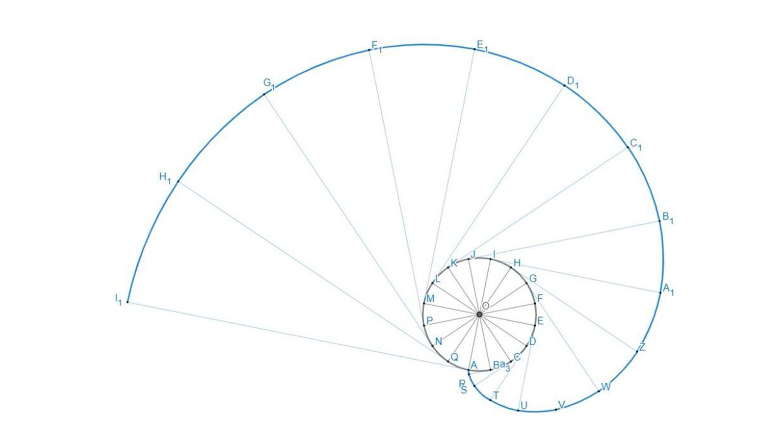
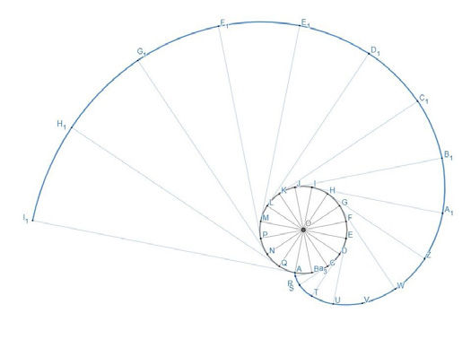
Before proceeding to analyze this possibility, it is worth noting that the involute geometry (and thus the shape of the tooth flank) is solely determined by the base circle from which the involute curve is “unrolled.” It is not the module or the pressure angle that defines the involute, but the base circle. The standard Equation 1 is not the definition of the base circle, but rather that of the base pitch. In Equation 1, the only truly physical quantities are the number of teeth (which can be counted) and the diameter of the base circle, which, although not visible to the human eye, uniquely defines the shape of the involute curve. Infinite combinations of module m and pressure angle α can lead to the same base pitch and thus the same base circle diameter, if multiplied by the number of teeth.
(1)
where
db is the base diameter
z is the number of teeth
m is the module (without subscript, considering spur gear)
α is the pressure angle
The module is therefore a conventional quantity used to define the size of the teeth (so much so that in AGMA documents, diametral pitch is found instead of the module). To simplify the approach, only spur gears are considered, so module and transverse module are the same.
A bit less conventional is the definition of the pressure angle, but there isn’t just one: there is a distinction between the operating pressure angle and the reference profile pressure angle (Ref. 4).
The logical sequence for defining the shape of gear teeth starts with fixing the base diameter and the number of teeth (and then cutting it from root to tip circle). The base pitch pb will then be uniquely determined.
(2)
[advertisement]
But this formula is also valid
(3)
At this point, there is only one degree of freedom: either the module or the pressure angle is fixed. Any combination of module and pressure angle that leads to the same base pitch will also result in the same shape of the tooth flank.
At an industrial level, however, it is convenient to follow the reverse path, having standardized the pressure angles and modules (Refs. 5,6).
Figure 1—Involute of circle.
As explained very well in (Ref. 7), since the phenomenon of cutting interference is greater when the hob’s addendum is larger, meaning when the distance from the tooth tip to the pitch circle is greater, it follows that reducing the hob addendum value is sufficient to reduce interference. Essentially, it involves rolling on a circle closer to the center of the gear.
Decreasing the pressure angle a, while keeping the base circle diameter db and therefore the profile tooth shape, means reducing the pitch diameter d, according to the formula (4). This is why reduced pressure angle hobs are discussed.
(4)
The main advantage of using this type of hob is the reduction in interference and thus the increase in the length of the contact profile, resulting in less stress on the tooth tip and consequently improving the efficiency of the hob itself.
It should also be noted that a hob with a lower pressure angle has a lesser tendency to transmit manufacturing and assembly errors to the tooth profile.
With this awareness, in the next of this first part of the paper, a sensitivity analysis of the pressure angle on the form diameter will be presented for various numbers of teeth. There will be the focus only on symmetric tooth profiles; a thorough treatment of the pressure angle on asymmetric tooth profiles can be found in (Ref. 8).
Case 1: “Classic” Gear, Profile II DIN 3972, Hobbing
The first analysis was performed on a standard gear, for academic purposes only, with no practical application. It was chosen to start with a hobbed gear module 1, with 23 teeth, pressure angle 20 degrees, x=0 and reference profile II DIN 3972 (Ref. 9).
Two phases were undertaken. In the first phase, the geometry of the reference profile of the tools was defined with different pressure angles to achieve the same geometry of the flank of the starting gear (including tooth thickness) and the same tip and root diameters. In the second phase, these tools were used to generate gears with different numbers of teeth.
Tool Preparation
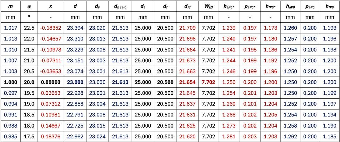
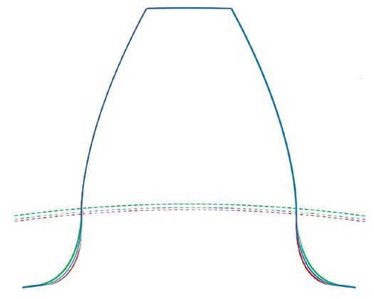
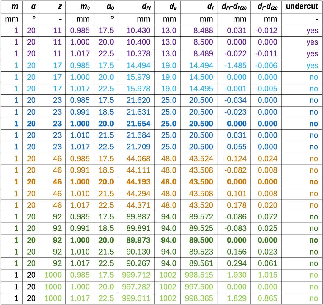
On a spreadsheet, the geometry of the “master” gear with a pressure angle of 20 degrees has been entered, as indicated in bold in Table 1. On the same spreadsheet, the column α has been populated with values from 17.5 to 22.5 degrees with a step of 0.5. For each row, the module has been calculated using Equation 3, keeping the base pitch of the reference gear fixed. The tip diameter da, root diameter df, and tooth thickness (span measurement) have been set equal for all rows. The pitch diameter d and V-circle diameter dv have been calculated on the same spreadsheet. These values have been entered into the KISSsoft calculation software to obtain the values indicated in red. In Figure 2, the geometries of the gears with pressure angles of 17.5, 20, and 22.5 degrees are visible. The rightmost 3+3 columns of the table constitute the definition of the tool reference profile for each gear. These profiles have been saved in the software’s database.
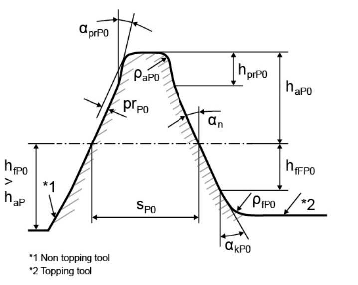
Table 1—Gear data for different modules and pressure angles, with fixed base pitch, tooth width, root diameter and tip diameter.Figure 2—Different root form circles due to different pressure angles (red for 17.5 degrees, blue for 20 degrees, green for 22.5 degrees).Figure 3—Reference profile symbols for hob in the db.
Gear Generation
With the newly defined tools, gears with different numbers of teeth were generated. It was required that, for the same number of teeth, the gears must have at least the same tooth thickness and the same tip diameter (the root diameter cannot be imposed, having defined the hob).
The obtained results, especially the root diameter and the root form diameter, are indicated in Table 2. The cutting pressure angle α0 identifies the hob defined in the previous section.
Table 2—Gear data for different number of teeth z and different hob pressure angles α0.
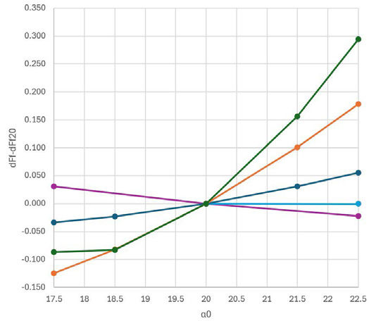
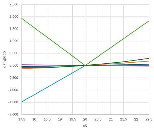
In Figure 4 (using the same colors), the difference between the obtained form diameter and that of the gear cut with the 20 degrees hob is shown for each number of teeth, for various hob pressure angles.
Figure 4—Variation of the root form diameter for different number of teeth z (see Table 2 for colors of z) versus hob pressure angles α0. In the upper plot the vertical scale is magnified between -0.15 and +0.35.
Analysis of Results
From the information presented in the previous clause, it can summarize that:
Although the tooth height was requested to be the same on all gears, with different numbers of teeth, the obtained tooth height is not.
The curvature of the involute flank is the same whatever the number of teeth.
The tool’s pressure angle affects the root form diameter of the cut gear, especially with a high number of teeth.
The impact of the tool’s pressure angle on the gear’s root diameter is often negligible, being two orders of magnitude smaller than its effect on the root form diameter (≈1/100).
If the tool’s pressure angle is greater than that of the gear, the root form diameter increases with the cutting angle, except in cases of undercutting.
For hob with pressure angles less than gear, the relationship is typically the opposite, although verification is advisable.
Case 2: Gear HCR 20 Degrees Hobbing and Grinding
As a second case study, a 52-tooth HCR gear with a 20 degrees pressure angle for automotive use, cut with a hob and finished by grinding, was selected. High contact-ratio or HCR gears are gears defined with a contact ratio greater than 2.0 (Ref. 10), sometimes called also long-addendum gears. The drawing also indicated semi-topping and tolerances on diameters and tooth thickness. To simplify the study, calculations were done without considering tolerances on tooth thickness and diameters. It was chosen to position on the maximum tip diameter and average tooth thickness.
Comparison was made only between the case with a 20-degree hob (as per drawing) and 17.5 degrees (actual), on this gear. Then, an analysis was carried out on what happens when using this same hob with a 78-tooth gear, with the same reference profile and tooth thickness as the Z52 gear.
Z52 Geometry
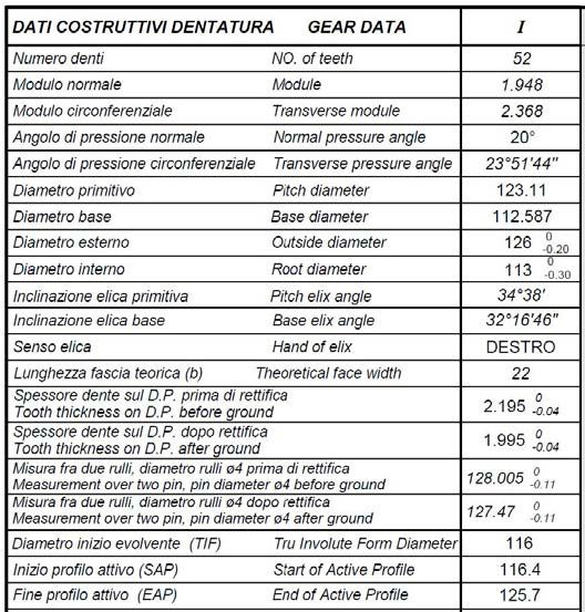
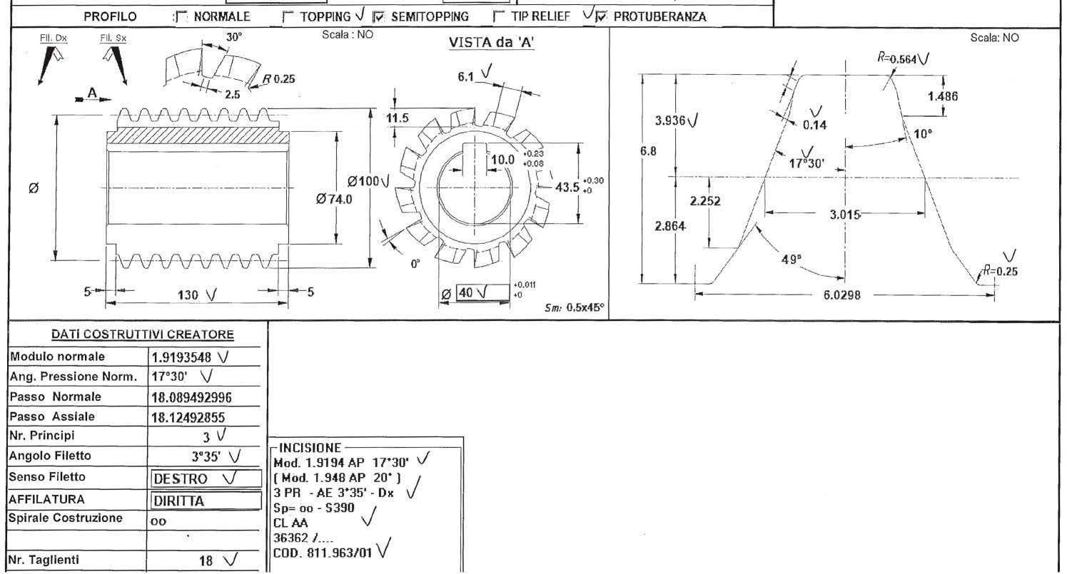
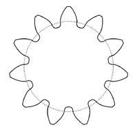
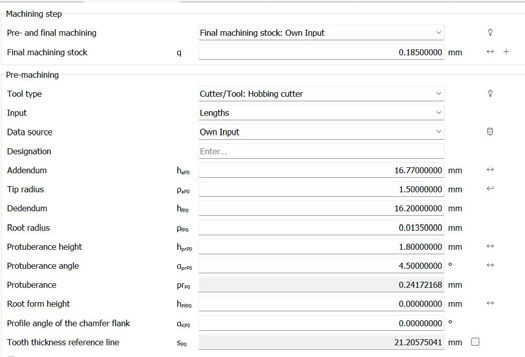
The gear in Figure 5 was cut with the hob in Figure 6, specially designed for this gear with a pressure angle less than that of the gear to reduce wear on the tip. The geometry of the obtained gear exactly reflects the requested one.
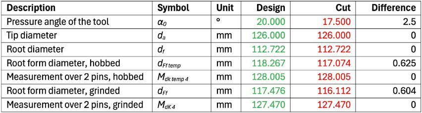
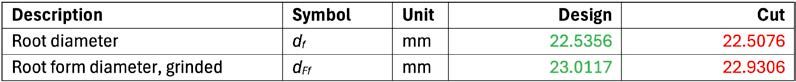
Figure 5—Table with data for gear Z52 from the gear drawing.Figure 6—The hob used to cut the gear Z52.Table 3—Comparison for gear manufacturing of the gear Z52.
A comparison was made between the geometry obtained with the indicated hob and a hob with the same pressure angle as the gear and the same values of protuberance and protuberance angle as the previous hob.
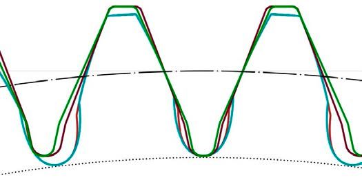
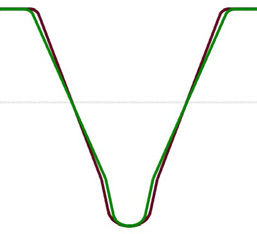
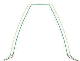
Figure 7 shows different geometries of the gear hobbed with a hob with pressure angle of 20 degrees in green and of 17.5 degrees in red. The involute profile is the same. In the same picture there are four elements: tooth form and hob profile for both cases. Involute profile is the same, root diameter is the same, but also after grinding, root form is different. In Figure 8 only hobs are shown.
Figure 7—Gear Z52 hobbing by hob with α = 20 degrees (green shades) and α = 17.5 degrees (red shades). The base circle is dotted. The dash-dotted circle is tangent to the reference line of the hob (the same in both cases).Figure 8—Hob with a= 20 degrees (green) versus α = 17.5 degrees (red).
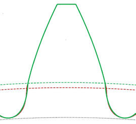
It is evident that the use of a hob with modified rolling brings benefits to the root form diameter after grinding (Figure 9), which is lower. In fact, to avoid meshing interference, it is important that the start of contact occurs in the part of the tooth where the involute is. That is, it is important that the root form diameter is lower than active root diameter (SAP, Start of Active Profile): dFf < dNf.
Figure 9—Root form circle (dashed) after grinding for the gear Z52 hobbed by hob with α = 20 degrees (green shades) and α = 17.5 degrees (red shades).
Z78 Geometry
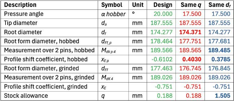
The same hob with a 17.5-degree pressure angle and protuberance was used to cut a gear with 78 teeth that had the same reference profile and thickness as the one with 52 just examined.
Complication arose due to the presence of the grinding step following the hobbing. Thus, two cases were examined: one with the same stock allowance also left on the Z52 gear, the other with the same root diameter as the design one. The results are shown in Table 4.
Table 4—Comparison for gear manufacturing of the gear Z78.
Z52 Strength
Although the scope of this paper focuses on production, it was deemed appropriate to investigate the consequences of modified rolling on tooth strength.
In both examined cases per gear Z52, the tooth flank shape is identical. Therefore, the contact pressure during operation is not affected by the production process with modified pressure angle, nor will it affect the resistance to macropitting.
The situation is different concerning the tooth root bending strength because the radius of curvature of root fillet is indeed different in the two cases.
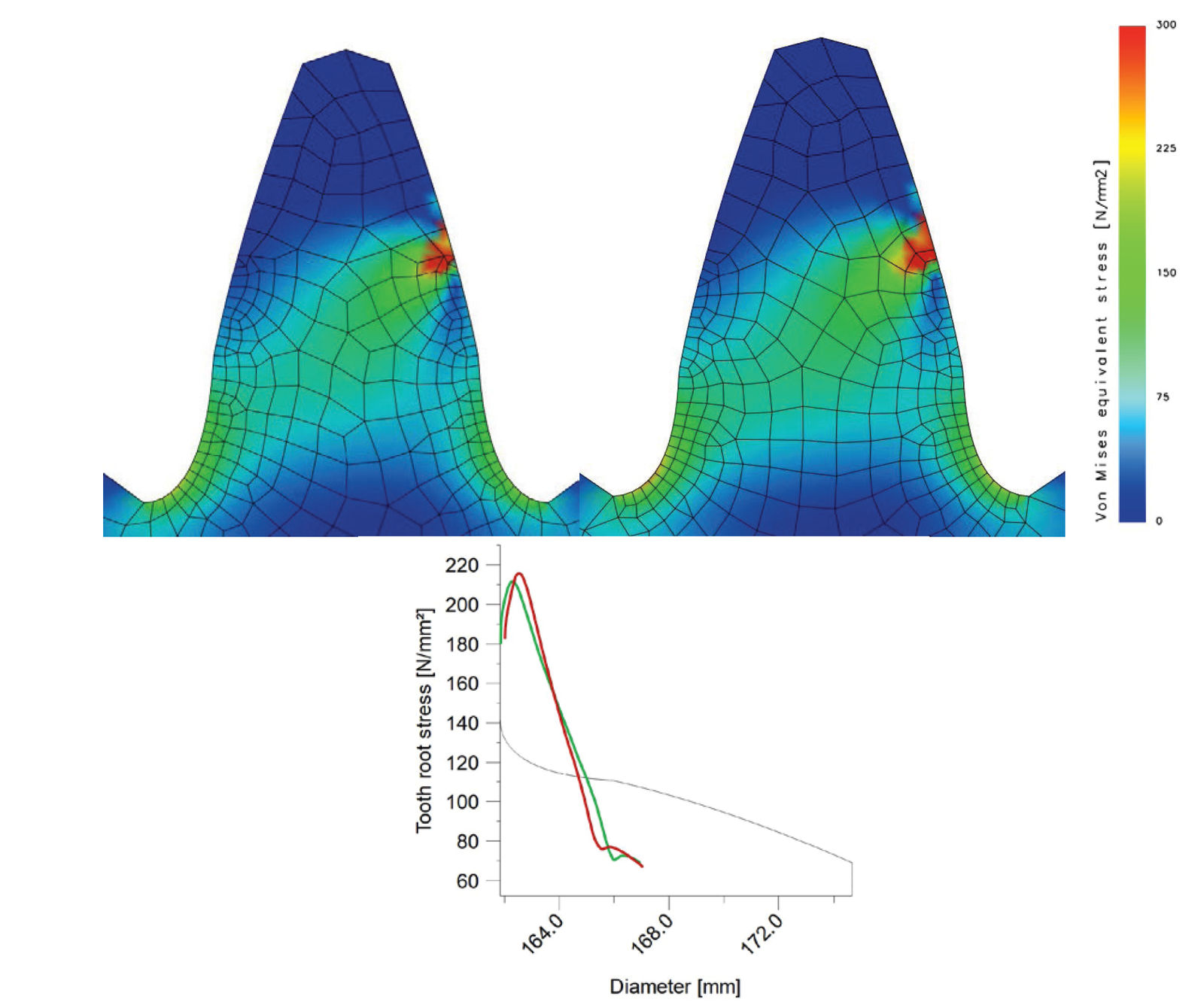
The FEM solver of the same software used for all previous calculations was used. A pair of identical Z52 gears with face width b = 10mm in a 1:1 ratio was assembled, and an arbitrary load of T = 450 Nm @ 10 rpm was applied. The absolute value of the calculated stress is not important; rather, the comparison between the stresses at the tooth root between the two geometries is crucial.
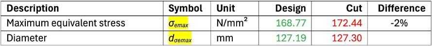
The results shown in Table 5 and indicate another advantage in using a hob with modified rolling for this gear: there is not an effective reduction of stress at the tooth root.
Table 5—Stress on the gear Z52 hobbed with hob pressure angle 20 and 17.5 degrees.
With only one case examined, it is not possible to establish a universal rule regarding the relationship between modified rolling and changes in bending strength. As seen in the “Analysis of Results” section, it is also not possible to establish rules for geometry. However, it is interesting to note that the tooth strength changes depending on the production process, particularly based on the pressure angle of the hob.
Figure 10—Von Mises equivalent stress on the designed gear (hobbed with hob pressure angle 20 degrees, green) and cut gear (hobbed with hob pressure angle 17.5 degrees, red). KISSsoft images with kind permission by KISSsoft AG.
Part Two: Hob Selection
Some drawings of cylindrical gears was examined, and efforts were made to determine as quickly as possible which hob could be used to cut them. The search did not always focus solely on hobs with the same pressure angle as the workpiece but also extended to a broader range, paying particular attention to the results obtained. The production process also includes a grinding phase after heat treatment.
Part of the searching process was already described in Ref. 11 to which reference is made for the flow diagram. Compared to what was reported in that paper, the software used has undergone significant updates: it is now possible to easily save a new hob in the database and view its dimensioned geometry to compare it with the drawing provided by the toolmaker. The search for the modified rolling hob also extends smoothly to slightly different base pitches (which will result in a nonconstant allowance as the grinding process takes place).
Manual and individual operations that the operator previously performed on the screen have been automated with the help of a Windows macro recorder. This allows for a quick and automatic generation of a list of usable hobs, with the geometric characteristics of the gear cut with each hob listed alongside.
Case 1: Industrial Gearbox Z30
A helical cylindrical gear of a small-sized parallel industrial gearbox is examined. The gear shown in Table 6 was designed with a profile II, achievable with a profile III hob + grinding. The drawing specifies “profile III + grinding,” and the strength calculations were performed with this geometry.
Table 6—Gear data.
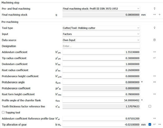
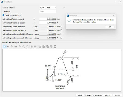
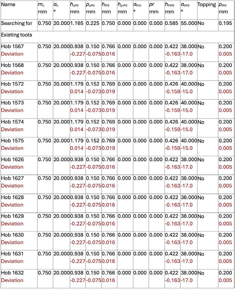
The gear data, including the required profile, were entered into the workshop’s calculation software (Figure 11). A search for suitable hobs was then conducted in the available database (Figure 11). It can be noted that the search can be extended by setting ranges for lengths and angles. The search results are in Table 7. Searching through a database of 850 records took only a few tenths of a second.
Figure 11—Windows with the definition of the profile designed for the gear Z30. KISSsoft image with kind permission by KISSsoft AG.Figure 12—Window of the hob searching for the gear Z30. KISSsoft image with kind permission by KISSsoft AG.Table 7—Result of the hob searching for the gear Z30 mn 0.75.
For this gear, the workshop did not deem it necessary to adopt modified rolling hobbing.
In Figure 13 and Table 8, the difference between the design profile (black) and the obtained profile (color coded) can be observed.
Figure 13—Geometry of the gear Z30 designed (green) and cut by “Hob 1572” (red), with and without stock allowance.Table 8—Comparison for gear manufacturing of the gear Z30.
Case 2: Tractor Gear Z11
A spur cylindrical gear for agricultural applications is being examined. The geometry is in Table 9 and Figure 14.
Table 9—Gear data of Z11.Figure 14—Gear geometry of Z11, with the base circle.
As in the previous case, after entering the gear geometry, a search was conducted in the current tool database to see if there was a suitable hob to cut the gear. The search did not yield any results (Figure 15 and Figure 16).
Figure 15—Window with the definition of the profile designed for the gear Z11. KISSsoft image with kind permission by KISSsoft AG.Figure 16—Window of the hob searching for the gear Z11. KISSsoft image with kind permission by KISSsoft AG.
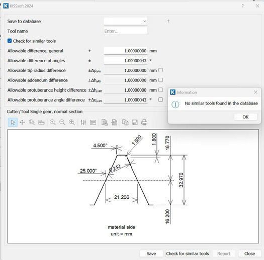
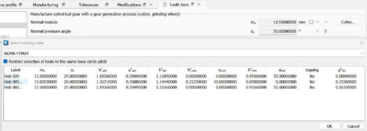
At this point, the decision was made to use modified rolling. In this case, there is no tool search feature like in the previous case, but there is the option to view all hobs that have the same base pitch as the gear with a tolerance of ±2 percent (Figure 17). The number of solutions found is fortunately small, so it is possible to calculate the three options individually. The results are in Table 10 and Figure 18.
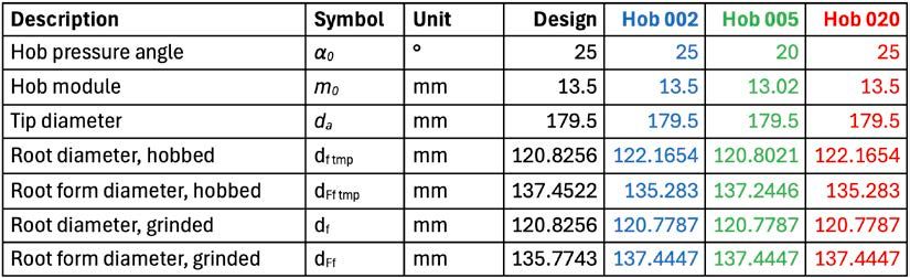
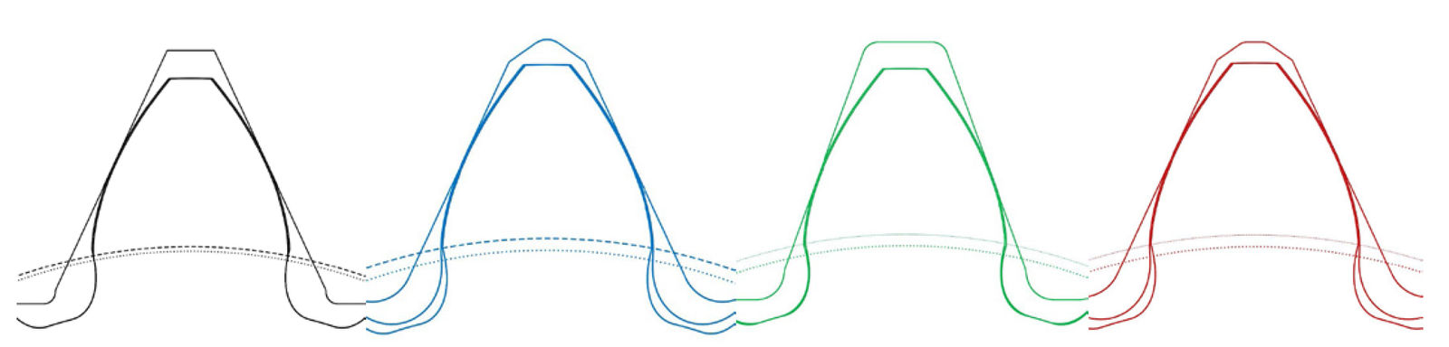
Figure 17—Window of the hob searching for the gear Z11. KISSsoft image with kind permission by KISSsoft AG.Table 10—Comparison for gear manufacturing of the gear Z11.Figure 18—Comparison for gear manufacturing of the gear Z11: tooth form with and without stock allowance, base circle (dotted), root form circle (dashed) and hob.
Hob 002 and Hob 020 are very similar, only the root radius value ρfP0 are different, but these hobs are not for topping, so the tooth form they generate are identical.
Hob 005 has protuberance and a lower pressure angle than the gear.
The gear is manufactured by the Hob 005.
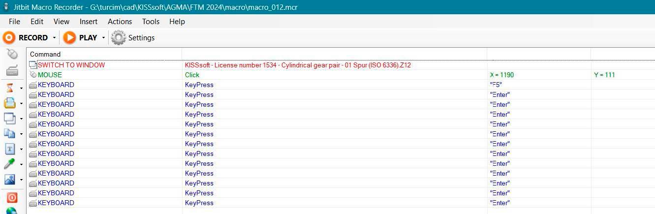
The list of hobs to be examined could have been very long (as in the previous example). Therefore, it was decided to automate the generation of Table 10 with a VBA macro in Excel. This macro, in turn, calls a Windows macro recorded on Jitbit macro recorder (Figure 19) that simulates the operations (mouse clicks) that the operator would manually perform for each row indicated in Figure 17.
Figure 19—Jitbit macro to run the tooth form calculation in KISSsoft.
The first line (in red) activates the KISSsoftwindow, where the file with the gear and the hob geometry are already defined.
The second line (in green) activates the “tooth form” window with the tool’s data.
The third line (in blue) performs the calculation using the F5 shortcut.
The remaining lines close any message or error windows that may appear when using an unsuitable tool by an ENTER key press.
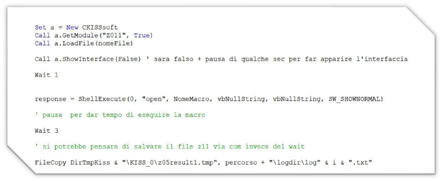
In Figure 20 there is the portion of VBA code that calls this macro from Excel after inserting the tool definition into the KISSsoftfile of the gear. In the Excel macro, there are “Wait” commands for the execution of operations on KISSsoft.
Figure 20—Part of the VBA macro code.
Open Issues
Taking into account what has just been described and what has already been reported in the two previous publications (Refs. 11,12), it is appropriate to address some open issues.
The procedure for automatically selecting the modified hob, however, computerized, can still be further optimized for speed. While for hobs with the same pressure angle as the workpiece, it is possible to use internal programming functions within the software used, this is not the case for selecting and calculating with modified hobs. The method described in this paper indeed uses a Windows macro recorder. This type of macro requires predefined latency times, calibrated for the worst-case scenario (slower), as the processing time for each tool is not known in advance. It is advisable to investigate how to switch from asynchronous to synchronous execution, which is significantly faster. Thankfully, in the new version of KISSsoft, released after the first draft of this paper, there is a function to calculate the tooth form, avoiding the external macro recorder.
It would also be advisable to investigate the strength of gears cut by modified rolling hobs. Sometimes, there may even be two meshing cylindrical gears that have been cut each by a hob with a different pressure angle. This results in a nominal pressure angle α for the gear pair, a working pressure angle for the pair αw, and two cutting pressure angles α01 and α02, which are responsible for the form factor (geometry factor) in the strength calculations according to ISO 6336 and AGMA 2001 standards. At present, the standards do not explicitly address the use of two different hob pressure angles. The same applies to calculation software based on these standards.
Smart Editing of the Gear Data
Before the conclusions, it could be interesting and funny note that the use of a different couple of “pressure angle & module” helped a designer to get a gear drawing accepted despite the reference diameter d was greater than the tip diameter da, i.e., outside than the gear. Everyone was aware of the strange shape of the gear in Figure 21A, but neither the workshop nor quality control were able to process a gear with d > da, mainly due to the tooth thickness being defined on the reference diameter. But since d = db/cos(α), it was enough for the designer to decrease α to decrease d below da.
Also the root radius was modified to get the same root tooth form diameter. The data of the “two” gears are in Table 11 and the position of the reference diameters are shown in Figure 21B.
Conclusions
Cutting with a hob having a pressure angle lower than that of the gear can be driven by two distinct needs:
“Dig” deeper into the workpiece and thus obtain a longer involute flank, effectively reducing the root form diameter.
Enhance the hob’s strength, particularly by increasing its thickness at the tip.
This technique is industry-specific: it is more common in transmission systems (automotive, agriculture), where the pressure angle is considered a variable, rather than a universal constant (either in design or production), as is the case of industrial gearboxes.
Opting to cut with a pressure angle different from that of the workpiece inevitably brings to complications in terms of calculation and management, especially when using a hob to cut a gear with a different number of teeth than the one for which it was designed.
This paper has presented the adoption of the selection of hobs with modified rolling, supported by extensive calculations on the company’s hob database. The procedure adopted aids the operator in choosing the most suitable tool based on the geometry of the gear that would be produced with each analyzed tool.
Acknowledgments
The author wishes to thank KISSsoft AG—A Gleason Company for the software.
Thanks also to the Italian companies Varvel/Mechnology, Bondioli&Pavesi and CEI for the support about this paper.
Bibliography
S. P. Radzevich, Ed., Dudley’s Handbook of Practical Gear Design and Manufacture, 2nd ed. Boca Raton: CRC Press, 2012.
G. Sanjay, “Corrected Lead Hobs. Understanding their use cases and machine settings,” Gear Technology, June 2023.
K. Liston, “Hob Basics—Part II,” Gear Technology, December 1993.
ISO 21771-1:2007 Gears—Cylindrical involute gears and gear pairs—Part 1: Concepts and geometry, 2007.
ISO 53:1998—Cylindrical gears for general and heavy engineering—Standard basic rack tooth profile, 1998.
ISO 54:1996—Cylindrical gears for general engineering and for heavy engineering—Modules, 1996.
G. Bianco, La dentatura con creatore. Bologna: Samp Utensili, 2004.
A. L. Kapelevich, Direct Gear Design. Boca Raton, Fla.: CRC Press, 2013.
DIN 3972:1952—Reference Profiles of Gear-cutting Tools for Involute Tooth Systems according to DIN 867, 1952.
C. D. Schultz, “High Contact Ratio Gearing: A Technology Ready for Implementation,” in Fall Technical Meeting (FTM), Arlington (VA): AGMA, 2014.
M. Turci, “Integrated optimization of gear design and manufacturing,” in Fall Technical Meeting (FTM), Chicago: AGMA, 2021.
M. Turci and V. Solimine, “Closed Loop for Gears: Some Case Studies,” in Fall Technical Meeting (FTM), Detroit: AGMA, 2022.
First presented at the 2024 Fall Technical Meeting (FTM), October 7–9, 2024, Rosemont, IL. Printed with permission of the author(s). Statements presented in this paper are those of the author(s) and may not represent the position or opinion of the American Gear Manufacturers Association.