[advertisement]

July 1, 2015


Inspection Reverse Engineering Ask the Expert

Determining Bull Gear Wear

Determining Bull Gear Wear

QUESTION

Expert Response Provided by Charles Schultz, PE:

We are currently experiencing wear on the bull gear on our converter at the steel plant. We want to be able to draw the original gear profile to compare this with the worn tooth before we decide on the next steps.
I have attempted this, but there is a correction factor given and I am unsure how to apply this. Could someone give advice on this?
Please find attached the PDF’s for the bull gear and the pinion gear.
They are old drawings! The wear is on the wheel.

Thanks for your very interesting question and the opportunity to revisit the beginning of my life in gears. As a freshman in high school drafting class, one of my assignments was drawing a spoked gear complete with the tooth flanks. Back in 1967, around the time your gear set was designed, this was an arduous task that certainly tested my skills with a compass and French curve set. Technology has improved since then; you have a number of methods available to you.

Method 1: tracing the existing tooth flank. You didn’t mention if both gear flanks were equally worn. In most cases they are not, so take advantage of symmetry and make a tracing of the leastworn flank, smooth out the profile with a thin flexible scale, and use it to check the depth of damage on the tooth flank. I have used this method in the field and think it will be sufficient for your purposes.

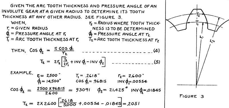
Calculation of gear radii based on tooth thickness, from Manual of Gear Design, by Eliot K. Buckingham and Earle Buckingham.
- Click image to enlarge

Method 2: use a manual drafting method from the Internet. The biggest change in engineering since 1967 has been the development of the Internet. Now in a matter of seconds you can seek the advice of dozens of people on how to do almost anything. Some of the advice is about as good as I would have gotten from a high school classmate; at least one carefully demonstrated method I downloaded was so bad it wouldn’t have passed that 1967 test. Others are very program-specific and may work better.

Share and save:


This article appeared in the July 2015 issue.


Read PDF

[advertisement]

Method 3: Develop a “point map” from tooth thickness equations. As you mention in your letter, some methods of plotting tooth profiles do not handle “non-standard” geometry well. Your gearset is on “standard centers” but the pinion outside diameter has been enlarged while the gear outside diameter has been contracted. In U.S. gear nomenclature this is a “long and short addendum” situation; the rest of the world calls it a positive and negative rack offset. No matter what you want to call it, there is enough information on the drawing to calculate the tooth thickness at the pitch diameter and the operating pressure angle at the pitch diameter. From those values it is possible to calculate the tooth thickness at any other diameter on the gear. Once you have the tooth thickness at the outside diameter, pitch diameter, and a couple of other diameters of your choosing, it is a simple matter of plotting the profile curve and making a template.

Close-up of the final tooth space
- Click image to enlarge

Method 4: Use a commercial program to produce a computer file of the tooth flank. If all of the above sounds like way too much work, there are several gear rating programs and even a few CAD programs with the capability of quickly producing a .dxf file of your gear profile. I used MITcalc’s spur gear routine and obtained the needed result within a few minutes. The most difficult part of the task was calculating the rack offset coefficient [X1]; several equally reliable methods are available online.

I am curious over what you hope to accomplish by measuring the wear step on a 43-year-old gearset. The specifications call for an induction-hardened pinion running against a 220 HB gear; with proper paste lubrication such gears can last 40 years or more, as your set demonstrates. Your gear could probably be re-cut to obtain a clean tooth flank and be returned to service with a new induction- hardened pinion (suitably adjusted on tooth thickness to maintain backlash) for another 40 years of work. If such a rework is not in the plans, you can certainly monitor the wear step to project the end of useful life or to evaluate the effectiveness of new lubricants. I have had excellent results with moly additives on moderately worn flanks. Your results may vary due to the depth of the existing wear step. Sometimes you can’t make the parts last forever.

About Author

Chuck Schultz, PE.,

Chuck Schultz, P.E., longtime gear man, AGMA member/contributor, and Gear Technology technical editor and twice-weekly blogger, can be reached at gearmanx52@ gmail.com.