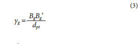
The angle Yg is:
where:
BgBg' is the length of arc BgBg'
dpt is the gear pitch diameter in the mesh with the shaper cutter
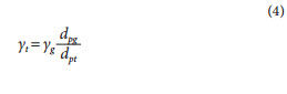
Then the point Agis in the position Ag' where the gear tooth profile 1' is tangent to the shaper cutter profile 2'. The line Ag'Bg' is rotated back relative to the shaper cutter center on angle γt that is:
where:
dpg is the gear pitch diameter in the mesh with the shaper cutter.
This movement puts the point Ag' in position At at the shaper cutter profile that corresponds to point Ag at the gear tooth profile. This approach allows definition of any shaper cutter profile point corresponding to a certain gear tooth profile point.
The gear pitch diameter in mesh with generating tooling (hob, rack or shaper cutters) is not necessarily equal to the operating pitch diameter with the mating gear. Accordingly, the pressure angle in mesh with the generating tooling can differ from the operating pressure angle. The pressure angle in mesh with the generating tooling selection is important. An extreme pressure angle (close to zero) results in a tooling profile that cannot sustain the required gear profile, due, for example, to the pointed tooling tooth tip or its overly small radius. It also adversely affects cutting condition, gear tooth profile surface finish, and tooling life.
One of the benefits of the generating gear process is the ability of using one tool (hob, rack or shaper cutter) for machining gears with different numbers of teeth. This allows reduction of tooling inventory and cost of low- and medium-volume gear production where tooling-share-per-one-gear is relatively high. In general, traditionally designed mating gears are machined with the same generating gear cutter; however, in mass gear production, gear cutting (or grinding) machines are typically set up to machine one gear and they use a dedicated set of tools — including the gear cutters.
Directly designed gears require a custom-dedicated generating tool for every gear with a different number of teeth. This increases tooling inventory and gear cost when production volume is low. Although, even in this case, application of directly designed gears can be beneficial if their improved performance justifies a production cost increase — like, for example, in aerospace and racing transmissions. In mass gear production, a share of custom-dedicated-machining-tool-per-gear is low and, as a result, the cost of directly designed gears becomes practically equal to traditional gears. This makes them applicable and sensible for automotive, agriculture, and other industries. Reverse-generating of the tooling profile from the gear profile is applicable for involute as well as for non-involute gears.
Contour machining. Contour machining (Fig. 8) is not a highly productive gear fabrication method; but, unlike form or generating machining, it does not require special tooling. This makes it very useful for gear prototyping and the quick fabrication of a relatively small quantity of gears.


Figure 8 a. schematic of contour gear machining: 1) gear profile; 2) cutting tool; 3) cutting direction; b. wire EDM gear cutting.
The contour gear machining processes include CNC milling, wire-cut EDM, laser cutting, water jet cutting, etc. In many cases, in order to achieve higher accuracy and surface finish, the contour machining process may require several passes, with the final pass removing just a small amount of material. While most of these processes are used only for spur gears, the CNC ball cutter milling can be used for helical gears as well. The contour cutting path (Fig. 9) is defined with off-set S from the nominal (average material condition) gear profile. This off-set contains one-half of the cut width Wc and some additional off-set that depends on the machining process. The additional off-set may include a stock for final machining, over-cut or over-burn (for wire EDM and laser machining), and/or a defective layer that should be removed by a tooth surface treatment operation; e.g. — polishing.

Figure 9 Contour cutting path: 1) nominal (average material condition)
gear profile; 2) tool path; machined gear profile; Wc - cut width;
S - tool path off-set.
Gear Forming
Forming gear fabrication processes. Plastic and metal injection molding; powder metal processing; net forging; stamping; die casting; extrusion; gear and worm rolling; etc. are very cost-efficient for mass-produced gear drives. Most of these forming gear fabrication processes have a similar tooling component that actually defines a gear shape and its accuracy, i.e. — a tooling (mold or die) cavity. Any gear forming process cavity is dedicated to a particular gear profile, which makes Direct Gear Design very acceptable for gear forming technology, as the production cost of the custom-optimized gears is practically the same as that of the similar-sized, standardized gears.
The cavity has a profile similar to the gear — but adjusted for shrinkage and warpage (Fig. 10) that greatly affects both gear size and shape accuracy. This makes the accurate prediction of shrinkage and warpage critical for all gear forming technologies — but particularly for the plastic injection molding process. Plastic gears often have intricate body shape, including ribs or spokes to maintain limited, maximum material thickness to exclude voids, and/or for weight and cost reduction. They also are often incorporated as one piece with other mechanism components such as, for example, shafts, cams, etc. These design specifics, in combination with a huge variety of available gear polymers and enhancing additives (for increased strength, thermo resistance, lubricity, etc.) make prediction of gear shrinkage and warpage an extremely difficult process. In many cases, gear molders rely on a sometimes costly trial-and-error method — with varying degree of success. Typically, this "educated guess" method works better for gears with relatively simple body shapes (like, for example, the flat uniform disks with small central holes) that are made out of generic unfilled polymers.
A totally different approach to molding distortion compensation is proposed in the literature (Ref. 3), referred to as the Genetic Molding Solution. Similar to how DNA contains genetic information about the entire living organism, the shape of the molded part reflects the originally designed profile, polymer material properties, tooling design, and molding process parameters. The Genetic Molding Solution method is based on mathematical prediction that defines a transformational function describing relations between the initially molded sample gear profile and its actual, initial cavity profile. Once this function is defined, the target gear profile replaces the first molded sample profile as the transformational function variable to calculate the final cavity profile. The transformational function is based on a system of trigonometric and polynomial functions.

Figure 10 Gear molding; 1) gear profile; 2) mold or die cavity profile.
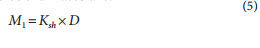
The initial cavity profile coordinates are:
where:
D target gear profile data set, presented as X,Y coordinate points of the 2D CAD model typically constructed for average material conditions
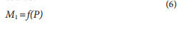
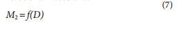
Ksh polymer linear mold shrinkage coefficient provided by the material supplier. These initial cavity profile coordinates M1 can be also presented as:
where:
P initial sample gear profile data set, presented as X,Y coordinate points provided by the CMM inspection of actual molded gear
f transformation function describing relations between the initial cavity and initial sample gear profiles
Then the final cavity profile coordinates are:
Unlike previously mentioned approaches, the Genetic Molding Solution method is based on the "black box" concept and uses only gear and cavity inspection results and math that define transformation function between them. It does not require knowledge of any specific data related to polymer material, tooling, and molding process parameters.
Practical application of this method entails eight steps:
(1) Target gear profile definition (data file #1). The X,Y coordinate points extracted from the gear CAD model present a desired nominal gear profile at average material condition. A number of these coordinate points are typically several-hundred-per-one-gear-tooth.
(2)Initial cavity profile definition. Initial cavity profile is the scaled up target gear CAD profile using the polymer linear mold shrinkage coefficient Ksh from its specification.
(3) Fabrication and inspection of initial mold cavity (data file #2). CMM inspection produces the X, Y coordinate points (several-hundred-per-one-tooth-space) accurately describing the initial cavity.
(4) Molding process optimization. Gears are molded using the initial cavity, without concern about the gear shape. A goal here is to achieve a stable and repeatable molding process with the part dimensional variation significantly lower than the required accuracy tolerances. Any material flaws — voids, for example — are unacceptable. Once this goal is reached, the molding process must be "locked in" and certified; no changes to the process are now allowed. Using the optimized process, several dozen gears are molded.
(5) Representative gear specimen selection. All molded gears are roll tested and inspection data is analyzed. The single-most representative preliminary gear specimen is selected. This specimen should have average statistical tooth-to-tooth and total composite errors (TTE and TCE).
(6) Gear specimen inspection (data file #3). CMM inspection produces the X, Y coordinate points (several-hundred-per-one-gear-tooth) accurately describing the initial cavity. Inspection data of the initial cavity and the gear specimen must have the same axes orientation to provide the each gear tooth and its cavity space accordance.
(7) Final cavity profile definition and fabrication. The Genetic Molding Solution software uses the gear specimen and initial cavity data (files #2 and #3) to generate a transformation function f. The target gear data (file #1) is then used as the variable of this transformation function to define the final cavity profile, or output data set. The same axes orientation of all three data file is absolutely critical. Any angular rotation or mirroring of the data points totally compromises the mold cavity adjustment results. The final cavity manufactured and then undergoes a CMM check-inspection.
(8) Final gear profile. And last, gears are molded using the final mold cavity. The CMM data of the molded gears should be identical to the specified gear profile, within the molding process accuracy variation.
For successful application of the Genetic Molding Solution method, the initial and final gear molding must be done with the same-batch polymer, on the same molding press, using the same tool. The current version of the software uses the 2D data sets and works well for spur plastic gears with relatively low face width. For helical and wide spur gears, this method should be used for several (typically 2 - 3) gear sections.
An example of this application method for the camshaft gear is shown in the Figure 11a. This gear is not particularly molding friendly; it has a metal, over-molded shaft, two cams, six spokes, and three injecting gates located in the middle of these spokes. Mold development for this gear using traditional methods requires considerable time and guesswork, and several mold cavity iterations. The Genetic Molding Solution method develops the desired cavity in short order by direct calculation — with only one extra (initial) cavity.
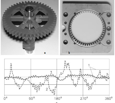
Figure 11 Genetic Molding Solution application: a) camshaft gear; b) gear mold
cavity; c) roll rest chart overlay; 1) total composite tolerance limits; 2) initial
specimen chart: 3) final gear chart.
Figure 11c shows a comparison of roll test graphs of the initial, most representative gear specimen with the final gear sample. The initial gear roll test measurements (TTE and TCE) greatly exceed the required accuracy level, but the final gear roll test results fit well inside the TTE and TCE tolerance limits.
The Genetic Molding Solution method significantly accelerates the injection plastic mold cavity development by eliminating the "guesswork" component of the final cavity prediction and providing its profile definition by use of direct calculation. It also can be considered for other gear forming processes that use mold or die cavities, such as power metallurgy, die casting, net forging, and more.
Summary
- Main methods of the directly designed gear fabrication are described
- Fly gear cutting process is illustrated
- Reverse-generating method for definition of the custom hob and shaper cutter profiles is presented
- Genetic Molding Solution technique for compensation of differential warpage and shrinkage for plastic injection molding tooling is explained


References
- Kapelevich, A. L. Direct Gear Design, CRC Press, 2013.
- Kapelevich, A. L., A. I. Tolchenov and A. I. Eidinov. "Application of the Fly Cutters in Experimental Production," Aviatsionnaya Promyshlennost, #3, 1985, pp. 39-40.
- Kapelevich, A. L., Y. V. Shekhtman and T. M. McNamara. "Turning an Art into Science," Motion System Design, August 2005, pp. 26-31.


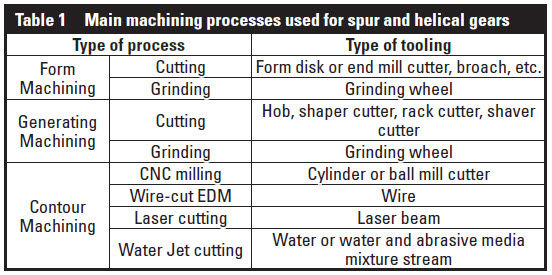
 Figure 1 Gear form machining: 1) gear profile; 2) tool profile.
 Figure 2 Gear fly cutting schematics: a) top view; b) right view; c) isometric view.
 Figure 3 Gear fly cutting: a) hobbing machine set-up; b) adjustable fly cutter with inserts.
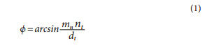
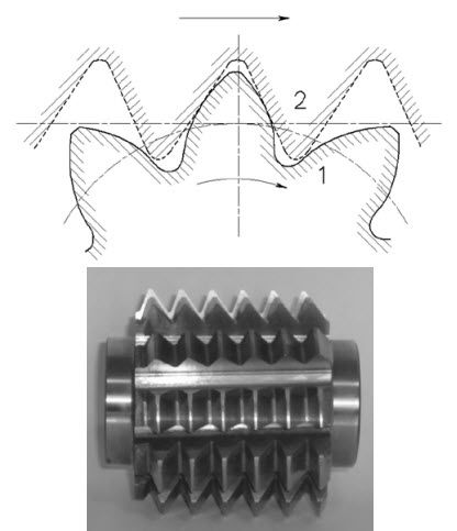 Figure 4 a. rack generating: 1) gear profile; 2) hob or rack cutter profile; b. asymmetric gear hob cutter.
 Figure 5 Generating rack profile definition: 1 and 1' - gear profile
positions; 2 and 2' - rack cutter profile positions; 3 - gear pitch
circle in mesh with rack; 4 - rack pitch line in mesh with gear.
Figure 5 Generating rack profile definition: 1 and 1' - gear profile
positions; 2 and 2' - rack cutter profile positions; 3 - gear pitch
circle in mesh with rack; 4 - rack pitch line in mesh with gear.
 Figure 6 Generating of external (a) and internal (b) gears: 1) gear profile;
2) shaper cutter profile.
Figure 6 Generating of external (a) and internal (b) gears: 1) gear profile;
2) shaper cutter profile. Figure 7 Generating gear shaper cutter profile definition for external
(a) and internal (b) gears: 1 and 1' - gear profile positions; 2
and 2' - shaper cutter profile positions; 3 - gear pitch circle in
mesh with shaper cutter; 4 - shaper cutter pitch circle in mesh
with gear.
Figure 7 Generating gear shaper cutter profile definition for external
(a) and internal (b) gears: 1 and 1' - gear profile positions; 2
and 2' - shaper cutter profile positions; 3 - gear pitch circle in
mesh with shaper cutter; 4 - shaper cutter pitch circle in mesh
with gear.