Second, to the mesh load factor Kγ, the face load factor KHβ is considered in the gear rating, e.g., along ISO 6336. It describes the evenness of the load distribution along the face width in the mesh between the sun and planet and planet and ring gear. If the load along the face width is evenly distributed, then, KHβ = 1.00 applies. KHβ is defined as the maximum value of the line load width, divided by the mean value, KHβ = max(w) / average (w). Since the Flexpin results in a movement of the planet parallel to the gearbox axis (see Figure 2, right), the load distribution remains symmetric to the planet’s face width and hence optimal (see Figure 3, right). The resulting KHβ are then typically KHβ = 1.15 and the modifications applied on the planets are only a slight flank line crowning.
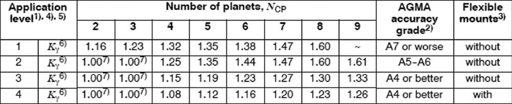
Figure 5—Kc values for different application levels and gear accuracy grades, with and without Flexpin (right side column labeled “Flexible mounts”), Ref. 7.
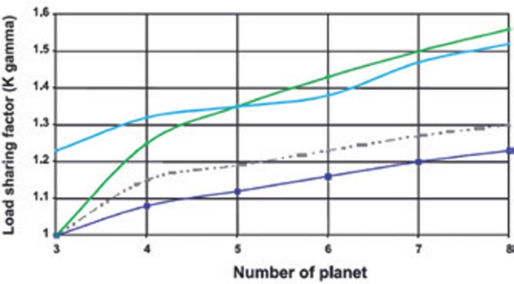
Figure 6—Load sharing factors (blue for measurement with Flexpin) compared to values stipulated in different guidelines. The measurement confirms that the use of a Flexpin allows for a much lower load-sharing factor to be used when compared to general design guidelines (Ref. 10).
Use of Flexpin in Wind Turbine MGBs
The single-wall carrier in combination with the concept of mounting the planet gears on Flexpins gives the design high reliability (because the contact between planet and sun flank and planet and ring gear flank remains near optimal for different torque levels) and high torque capacity (because of the elevated number of planets). Numerous gearbox designs for wind turbine MGBs using Flexpins exist. However, it must be said that the use of the Flexpin concept is not used in high numbers. Most of the leading MGB OEMs companies do not use the Flexpin in their design; this is a strong indicator against the use of the Flexpin for standard gearbox designs. It means that there are probably good reasons not to use Flexpins in a conventional gearbox design and this means that the advantages and disadvantages of the Flexpin design must be carefully considered.
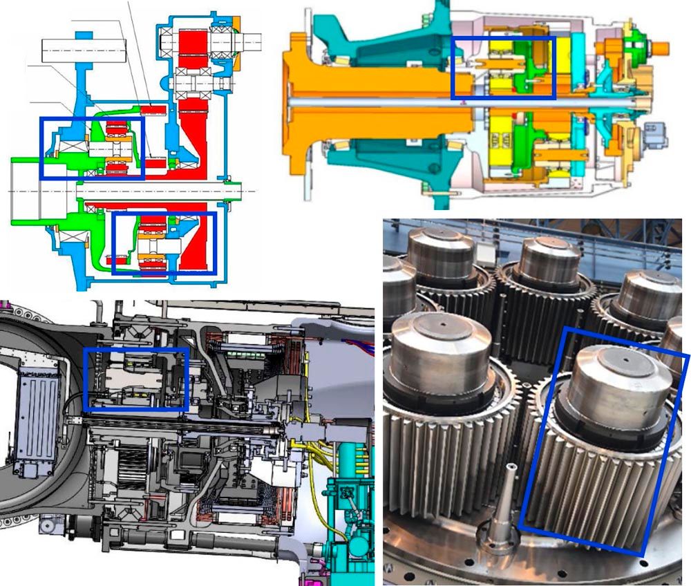
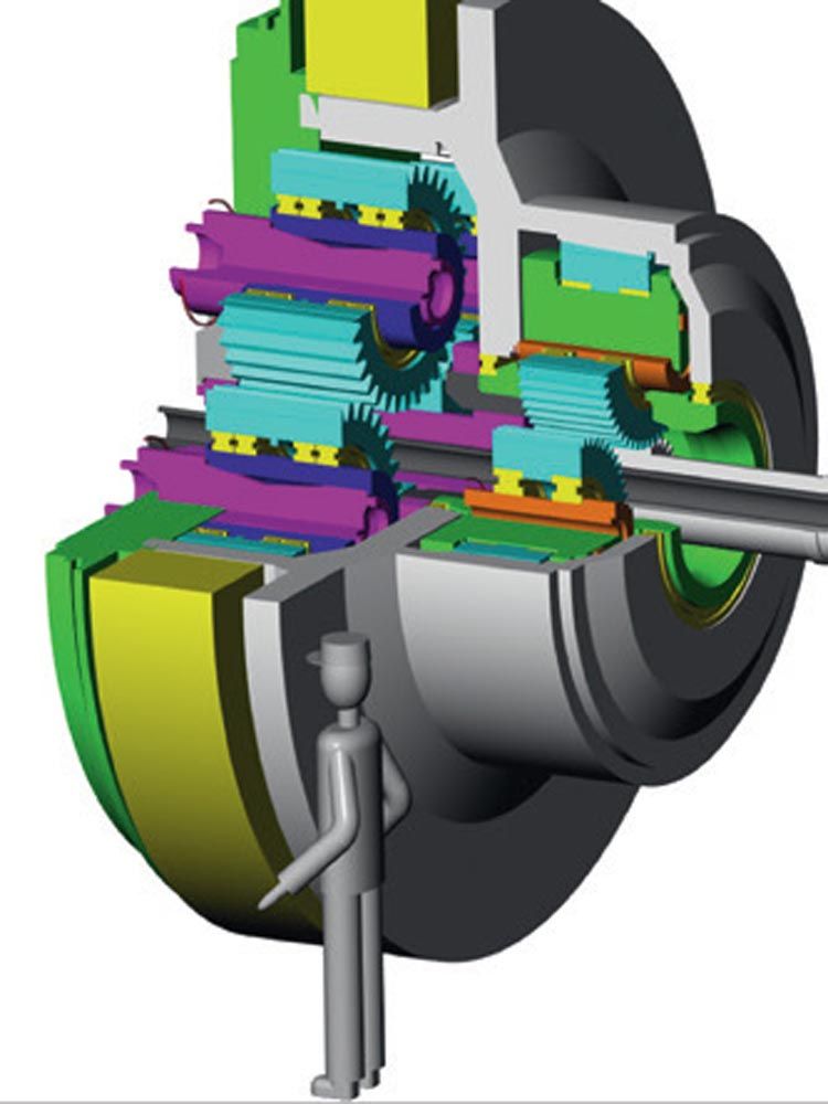
Figure 7—Top left: Gearbox design by MAAG (Ref. 17), believed to be the first wind turbine MGB featuring Flexpins. Top right: Design of a wind turbine MGB using Flexpins, having a compound planetary arrangement (sun gear of second stage connects to the ring gear of first stage (Ref. 19). Bottom left: SCD gearbox designed by the author (Ref. 9). Bottom right: Planetary stage with seven planets, 7 MW wind turbine MGB by WIKOV (Ref. 18). Flexpin highlighted in cross-sectional images.
Flexpin Use in SCD Turbine Main Gearboxes
Flexpin as Used in SCD Gearboxes
Figure 8 of Flexpins manufactured by the author shows a similar design. The conical shapes are designed such that an almost constant stress level along the pin axis results, thereby maximizing the utilization of the material or reducing the mass of the pin. The parts shown are hard turned, before machining of the threads for the locknuts and heat treatment. The critical areas of the pin, particularly the fillet radii, are polished to reduce the effect of surface roughness on their strength. Also, pins are nitrided, resulting in a hardened outer layer with very little deformation during the heat treatment process. The hardened layer is thin, less than 1 mm but increases the stress at the surface (where the highest stresses are present) considerably.
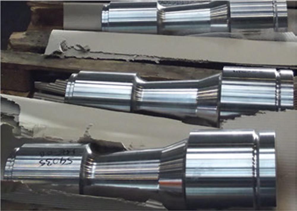
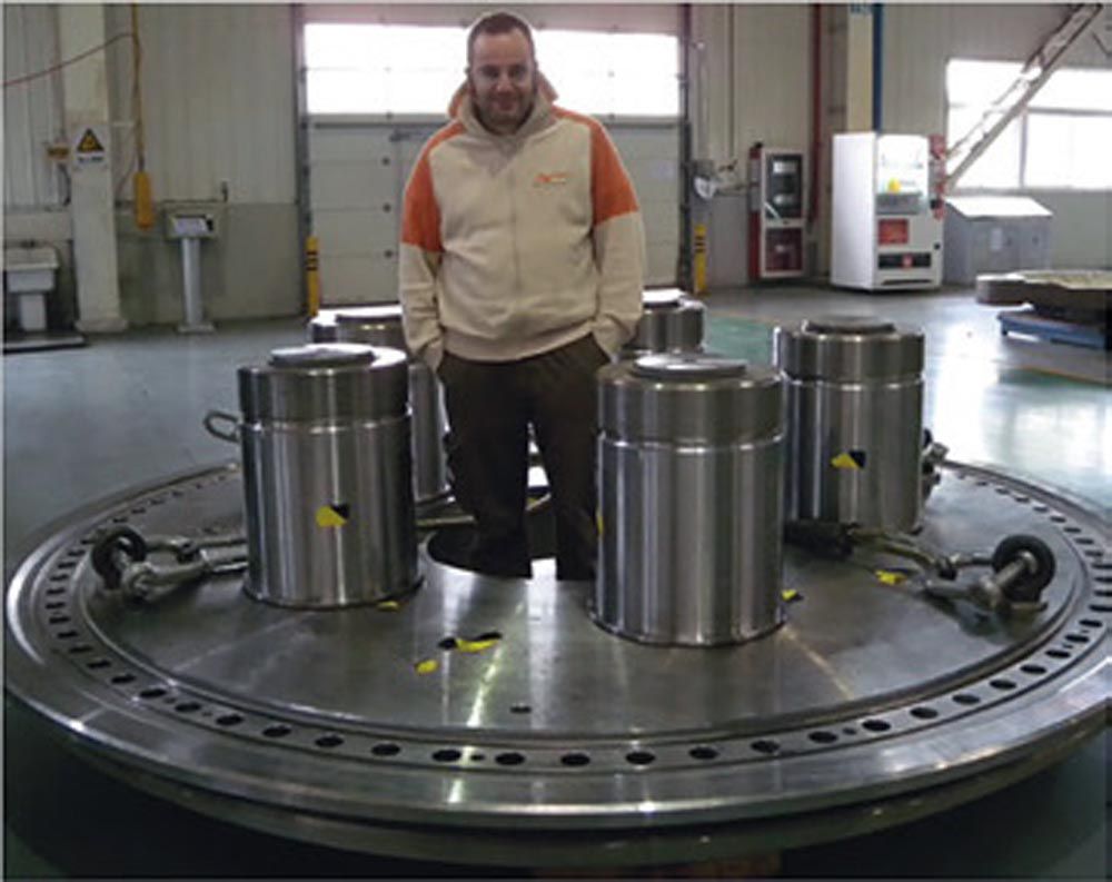
Figure 8–Flexpin pins, awaiting transport to heat treatment.
The right pin is cooled down and inserted into the sleeve.
Calculation of Load Distribution
The planetary stage having five planets supported on Flexpins is modelled as a combination of springs and gaps. The springs model the stiffness of the parts while gaps are used to model manufacturing errors. Errors considered using gaps included
- Pitch error in the teeth
- Differences in the bearing clearances
- Misalignment between Flexpin pin and sleeve
- Positioning errors of the Flexpin in the carrier
The starting point is the spring model of a planetary stage with five planets as shown below. From the carrier torque and the center distance, a force Ftot is determined that is then distributed—as a function of the spring stiffness values and the gaps (position errors) into the five planets. In the five planets, the five F1, F2, F3, F4, F5 are present. They are not exactly the same, Kγ is then Kγ = max(F1, F2, F3, F4, F5) / average(F1, F2, F3, F4, F5). Each planet is further broken down into a more detailed spring system as shown below.
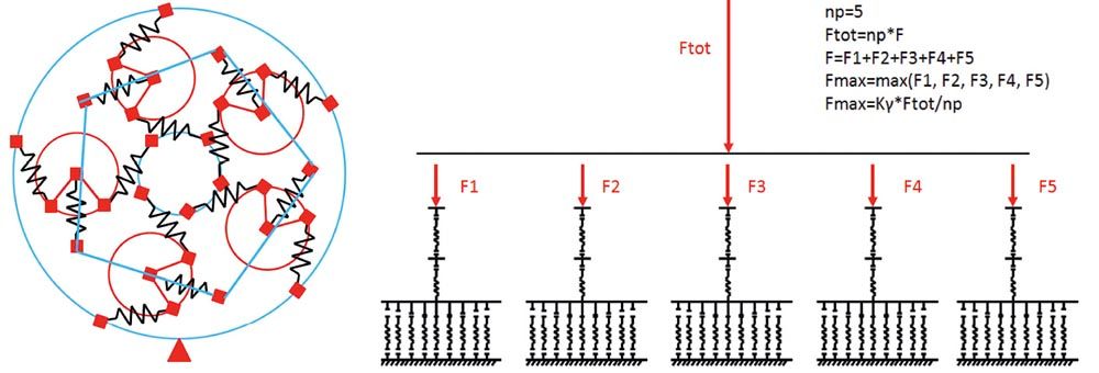
Figure 9—Spring model of a planet stage with five planets. Left: meshes and Flexpins as springs. Right: Corresponding model with gear meshes modeled finely.
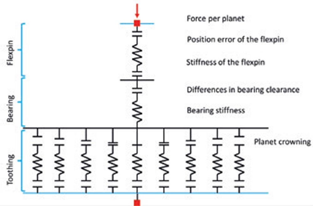
Figure 10—Spring-gap model of one planet. Note the spring representing the Flexpin.
The contacts between ring gear and planet and between sun and planet are represented by one contact. The crowning is considered, it varies over the tooth width. The pitch error is modeled as a gap in the contact between the planet and the sun/ring gear.
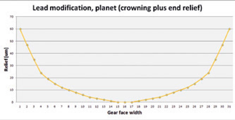
Figure 11—Planet modification combining slight crowning with linear end relief on either side.
For the different errors considered in the model, the following ranges are defined:
- Pitch error of teeth: a gear quality of Q=6 is assumed, resulting in +-20 μm possible pitch error in the mesh. The mesh itself is represented by 31 individual springs to model also a crowning.
- Variation of the bearing clearance: For a bearing with d=320 mm and clearance C3 (305 μm to 225 μm) a variation of ±40 μm is used, this may be conservative.
- Flexpin: Here, two errors are considered. The positioning error (using quality IT6 on the center distance, giving a tolerance of ±80 μm, again somewhat conservative) and the concentricity error (between pin and sleeve, assuming IT5, giving ±50 μm, again somewhat conservative).
These errors were then determined for all five pins using Microsoft Excel number generator. A total of 20 random numbers for each of the errors in the five Flexpins were used and added up giving twenty experiments. Within the above-defined range of the errors, a random number / value for the error was used (using Microsoft Excel to determine a random number using a constant probability distribution). So, a random error in the bearing clearance variation (variation from bearing to bearing) of 40 μm to +40 μm, a random error in the flex pin position of -80 μm to +80 μm, a random error in the gear pitch of -20 μm to +20 μm and a random error in the concentricity of the Flexpin pin to sleeve of -50 μm to +50 μm was defined. The random errors were then added up to give five total errors for each planet. The procedure was repeated twenty times to give twenty random error distributions for the planetary stage.
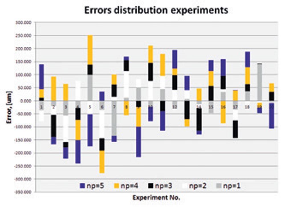
Figure 12—Resulting manufacturing errors for the five planets, shown for 20 random experiments.
Now that the manufacturing errors and gaps in the gear meshes are defined, the force distribution among the five pins may be calculated from the known spring stiffness values. This is done for 20 random manufacturing error groups. From the Flexpin forces F1, F2, F3, F4, F5, load distribution factor Kγ may be calculated. The average value is found at Kγ = 1.13 and 95 percent of all values are below Kγ = 1.14.
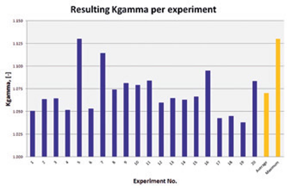
Figure 13—Resulting Kc for 20 experiments, average and maximum value.
Experimental Measurement of Load Distribution
The SCD drive train was subjected to operating loads and the Flexpin deformation was measured. Measurement over time showed a fluctuation of the load-sharing factor, possibly induced by the heavy masses present in the gearbox that are superimposed to the external torque load. Two types of tests were conducted, one where only torque load was applied and a second test where the torque load was superimposed with a bending moment corresponding to the bending moment as experienced in a typical wind situation. Note that the bending moment has a major influence on the load sharing in this design (see exploded view below) as the gearbox is an integral part of the whole load-bearing structure. Also, in the load path there is the main bearing integrated into the gearbox and any clearance or stiffness of the main bearing contributes to a tilting of the planet carrier and therefore affects the load distribution. This is an effect that was not relevant or not considered in all other studies shown here and the additional results generated in this study are worth mentioning. The resulting load sharing factor Kγ = 1.23 was found, well above the load sharing factor under pure torque only. However, the value found in the measurement confirmed the value used for design at Kγ = 1.25.
Note that the above measured value at Kγ = 1.12 happens to correspond to the value given in AGMA 6123, for five planets, application level 4 with flexible mounts. Application level 4 with flexible mounts is for “high quality, high speed, gas turbine/generator drives, military marine” applications. Wind turbines are classified there as application level 2 in general, there is no specific application level for wind turbines with Flexpins mentioned.
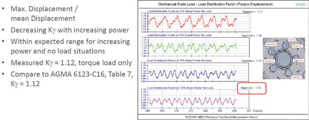
Figure 15—Measurement of load sharing factor (calculated from five measurements of Flexpin deformation), only torque applied, for different torque levels (Ref. 9).
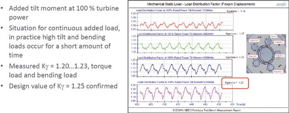
Figure 16—Measurement of load sharing factor (calculated from five measurements of Flexpin deformation) with bending moment applied, for different torque levels (Ref. 9).
Shape Optimization
Motivation
During the above design, analysis, manufacturing, and testing of the Flexpins, it became apparent that manufacturing costs are largely independent of the pin shape while the load distribution among the planet greatly benefits from a lowered pin stiffness. Optimizing the pin shape to reduce its stiffness while keeping stress levels was attempted to have the best possible design if and when the need for a higher torque main gearbox arises.
Flexpin Pin Shapes Compared
Others have worked on optimized pin shapes earlier. In the study (Ref. 6), five designs are compared.
- Conventional design / no Flexpin
- Flexpin with original design by Ray Hicks (see Figure 17, left, for pin shape)
- Flexpin with circumferential groove (see Figure 17, second from left, for pin shape)
- Flexpin with spindle shape (see Figure 17, second from right, for pin shape)
- Flexible conventional planet pin supported on both sides (see right side of Figure 17)
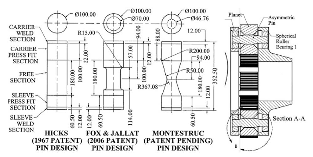
Figure 17—Different pin shapes compared (Ref. 6).
The target in these optimizations is to achieve the lowest stiffness (hence best load sharing among the planets) while not overstressing the pin. While the original Flexpin (Figure 17, left) was strictly cylindrical, the most common design uses a series of several cylinders (second design from left). Montestruc then further improved the design by using two tapered halves. The purpose of the below optimization is to further refine this design to achieve near-constant stress distribution along the pin.
Shape Optimization
Based on the bending moment distribution along the pin, the required diameter at each point along the pin axis may be determined, resulting in an even stress level along the pin length (Ref. 20). Bending moment from left to right along the pin length is shown below.
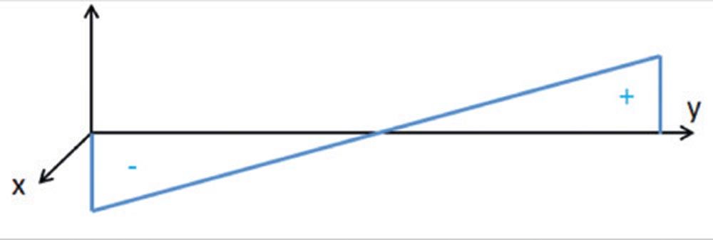
Figure 18—Bending moment over free length of Flexpin (vertical axis) vs. length / y-coordinate.
Bending moment, bending stress and required moment of resistance are then:

(1)
From this, the required pin diameter along the coordinate y can be calculated:
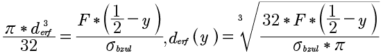
(2)
Note the above only considers bending moment. The resulting function, if plotted, gives a convex shape of the two halves of the pin, see below Figure, left:
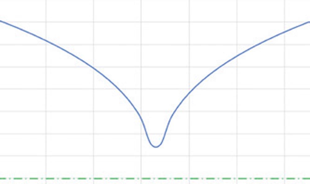
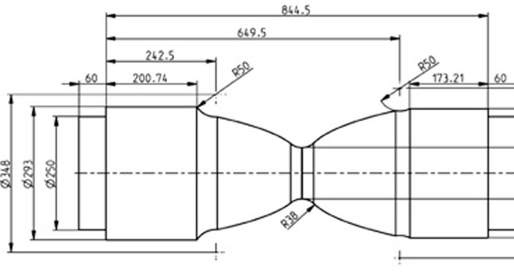
Figure 19—Resulting pin shape, considering bending stresses only, such that the stress level is constant along the pin length (note that in the middle, theoretically, the pin diameter would be zero).
The above shape (Figure 19, left), having a constant nominal bending stress along the longitudinal axis, serves as a basis for to design of the pin shape (Figure 19, right). In the middle of the pin, a cross-section is added such that the shear stress in the thin section is like the bending stress to the left and right. Furthermore, radii and relief grooves are incorporated, minimizing stress raisers. Analytical and FEM-based calculations are then used to confirm the even stress distribution below acceptable levels. Note that since the press fits between the pin of the Flexpin (2), on the lower left side of Figure 20, and the single-walled carrier (1) has a different stiffness than the one to the sleeve (3). Detailed FEM calculations showed that it is necessary to change the shape of the pin to an asymmetrical shape as shown in Figure 20, right.
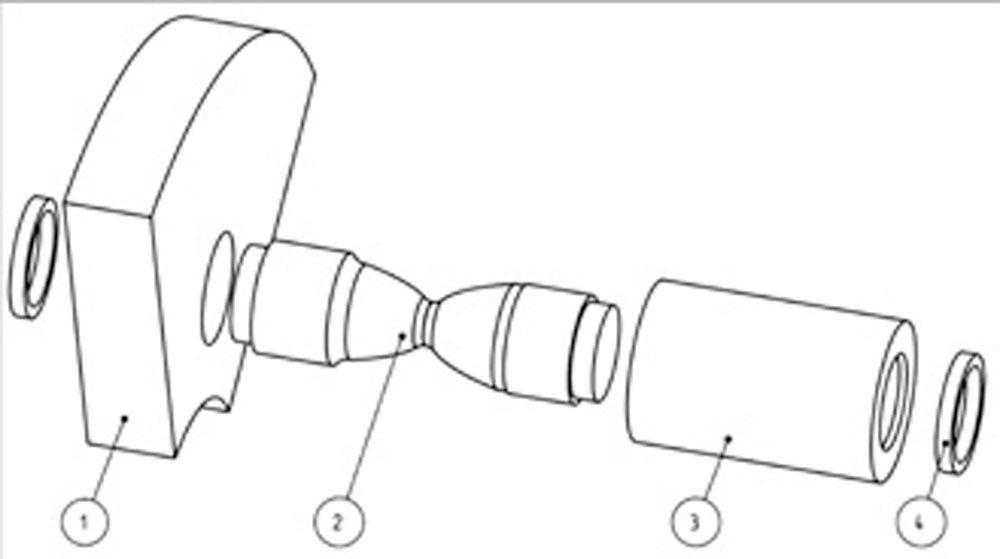
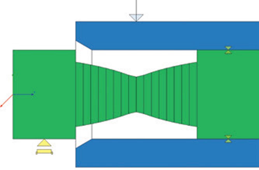
Figure 20—Top: Design with optimized pin (2) shape. Single-walled carrier (1) and sleeve (3). (Ref. 20). Bottom: Calculation model using two Timoshenko beams (green representing pin, blue representing sleeve). Press fit between pin and carrier and between pin and sleeve is by rigid connectors (yellow symbols).
Comparative Strength Assessment on Shape Optimized Flexpin Shapes
For a wind turbine of similar design as discussed above, now targeting 8 MW instead of 3 MW rated power, an initial design of a shape-optimized Flexpin of approximately 600 mm length was assessed. As the FEM analysis and stress assessment using gearbox torque time series is computationally expensive, a preliminary assessment using the nominal stress concept based on FKM guideline (Ref. 1) is used. FKM guideline method is preferred over DIN 743 (Ref. 2) here as the latter neglects shear stresses from shear forces which are relevant for short beams as present in the Flexpin pin. For this, the Flexpin design for which the FEM-based verification had been done and accepted by the certification agency along typical guidelines Refs. 3 and 4 earlier (for the 3 MW gearbox), were analyzed using FKM guidelines. In this, the rated torque, and a conservative assumption for the stress ratio (R=0) were used.
The resulting safety factors were then compared, and it was found that the Flexpin for the 8 MW gearbox displays slightly higher safety factors than the Flexpin for the 3 MW gearbox. In this, the technological and statistical size factors Kdm and Kdp are considered to account for the influence of larger part size for the 8 MW gearbox. Ultimate tensile strength at 1,250 MPa and yield strength at 1,050 MPa values were defined as target values in the manufacturing drawings and discussed with the forging company producing the forgings with a machining stock. The effect of the surface hardening by nitriding was neglected in the strength assessment as the part size was now such that the hardening depth achievable by nitriding was in the range of the depth of the stress concentration.
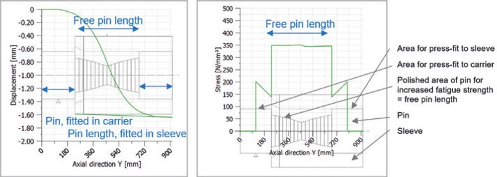
Figure 21—Left: Deformation. Right: Equivalent stress. Note: the nominal stresses (not considering notches/fillet radii) are now nearly constant along the free pin length.
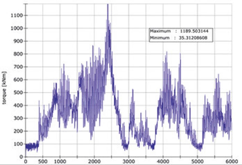
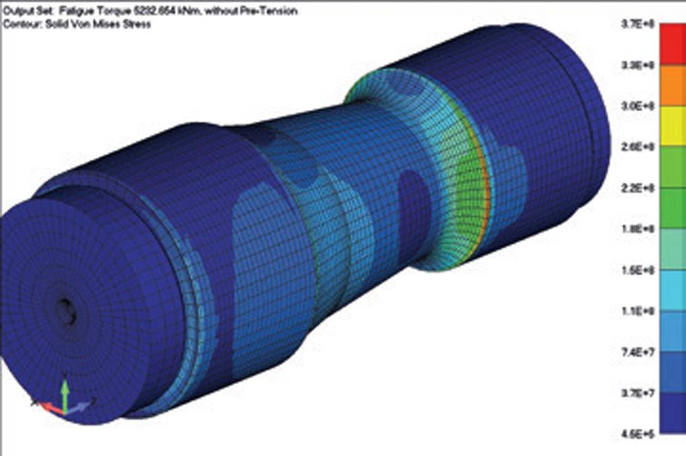
Figure 22—FEM based strength assessment of 3 MW MGB Flexpin. Left: Time series of torque used for fatigue rating of Flexpin. Right: Stress level in the pin at nominal torque.
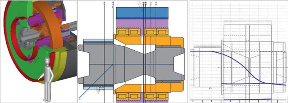
Figure 23—Left: 8 MW MGB model for analytical strength assessment. Middle: Flexpin model with optimized pin shape for comparative strength assessment. Right: Flexpin deformation (blue lines) based on Timoshenko beam model calculation, indicating that shape of Flexpin is suitable for keeping planet gears in parallel to gearbox axis under load.
Conclusion
Flexpins are used in wind turbine MGB and other planetary gearboxes. It helps threefold:
- It improves the load sharing among the planets, in particular if the number of planets is higher than three. This is expressed in the gear rating with (a low) factor Kγ.
- It improves the load distribution along the gear face width. This is expressed in the gear rating with (a low) factor KHβ.
- It allows for the use of single-walled carriers where the planet pins are supported on one side only.
A low stiffness of the Flexpin is desirable to maximize the effect in the above points 1) and 2). While a thinner Flexpin pin results in lower stiffness, it also results in higher stresses. Optimizing the pin shape allows for a constant stress design, thereby maximizing the flexibility while keeping the stress levels within acceptable limits. As opposed to prior state-of-the-art, where cylindrical and other shapes are used, a parabolic shape, used in a symmetrical arrangement, is proposed here.
Furthermore, using simple spring models, the load-sharing factor Kγ may be predicted reasonably well. A gap–spring model was used to consider manufacturing and positioning errors along with component and gear mesh stiffness values. Numerical experiments using random error distributions were conducted and the 95-percentile value for Kγ was found at Kγ_95 percent = 1.14. This was close to the value found in torque load test at Kγ_torsion = 1.12 yet still somewhat conservative. If in the test also bending loads were introduced, the Kγ value reached up to Kγ_bending = 1.23 which was still within the range defined by the value used in the gear design, as stipulated in design guideline (Ref. 3), at Kγ_design = 1.25.
As with respect to the design and manufacturing process of the Flexpin, experience has shown that:
- The use of a beam model for initial design of the Flexpin, in particular the pin, is sufficiently accurate for a preliminary design only.
- The beam model, where typically the pin is rigidly supported on one side to represent its fit in the carrier and where the pin and the sleeve are typically rigidly connected to represent the fit between the two, is not accurate enough for a final design.
- FEM calculations considering the non-linear behavior of the press fits are required for design and verification of the final shape of the Flexpin and its deformation behavior.
- By introducing tilting stiffnesses in the beam model and tuning them such that the beam model yields similar deformation results as the FEM model, greatly improves the accuracy of the beam model. This lowers the number of FEM calculations needed to arrive at a final pin shape.
- Relief grooves in the pin lower stress concentrations induced by the press fits.
- Pin ultimate tensile and yield strength may be defined at 1,100–1,200 MPa to 900–1,000 MPa respectively. These levels may be achieved with commonly used steels such as 34CrNiMo6 and heat treatment applied after near-net shape machining.
- Nitriding, induction hardening, or case carburizing combined with polishing of the pin results in elevated part strength levels. The strength increase was assessed by introducing respective rating factors as per Ref. 1 and Ref. 2.
- The author has no experience with the shot peening of the Flexpin pin. Industry experience with similar parts proves the potential of the process.
- The press fits used were at 0.15 percent overlapping and proved to be working well in the field. No oil creep through the press fits was observed.
- A grinding or hard-turning operation to finalize the bearing seat after fitting the sleeve onto the pin is necessary.
The use of Flexpins in gearboxes allows for maximized torque density. Due to the higher material and manufacturing costs, it has not gained wide use. However, in gearboxes where the planet carrier only has one wall, it indeed solves the resulting issues elegantly.

References
- FKM-Guideline, Analytical Strength Assessment, 6th Edition.
- DIN 743-1, 2, 3, Tragfähigkeitsberechnung von Wellen und Achsen.
- Germanische Lloyd Rules and Guidelines Industrial Services, Guideline for the Certification of Wind Turbines, 2010.
- ISO 81400-4:2005, Wind turbines, Part 4, Design and specifications of gearboxes.
- Höller, A., Zumofen, L., Kirchheim, A., Dinner, H., & Dennig, H.-J. (2020). Additive manufactured and topology optimized Flexpin for planetary gears [Conference paper]. In M. Meboldt & C. Klahn (Eds.), Industrializing Additive Manufacturing : Proceedings of AMPA 2020 (pp. 337–356). Springer. https://doi.org/10.1007/978-3-030-54334-1_24
- Montestruc, “Influence of Planet Pin Stiffness on Load Sharing in Planetary Gear Drives,” Journal of Mechanical Design, 2011.
- ANSI/AGMA 6123-C16, Design Manual for Enclosed Epicyclic Gear Drives.
- NASA Technical Memorandum 107275, Effects of Planetary Gear Ratio on Mean Service Life.
- Dinner et al., SCD SuperCompactDriveredesigned and sucessfullytested to meet floating offshore challenges, ATK & CWD 2019.
- TIMKEN, Integrated Flexpin Bearing for Epicyclical Gearing Systems, The TIMKEN Company.
- LaCava et al., Gearbox Reliability Collaborative: Test and Model Investigation of Sun Orbit and Planet Load Share in a Wind Turbine Gearbox, Conference Paper NREL/CP-5000-54618, April 2012.
- Giger et al., High-Efficiency High Torque Gearbox for Multi Megawatt Wind Turbines, Scientific Proceedings VIII International Congress “Machines, Technologies, Materials” 2011.
- Wang et al., Load Sharing Performance of Herringbone Planetary Gear System with Flexible Pin, International Journal of Precision Engineering and Manufacturing, 2019.
- Tsai et al., Design and Analysis of the Planetary Gear Drive with Flexible Pins for Wind Turbines.
- Giger, Planetenkoppelgetriebe in Windenergieanlagen mit flexibler Planetenlagerung, DMK 2003.
- US Patent 3’303’713.
- Raeber, R.; Weller, U.; and Amato, R., “A New Gearbox Generation for Vertical Roller Mills”, Technical Paper, MAAG Gear AG, 2006.
- https://www.wikov.com/en/mechanical-gearboxes/according-to-application/wind-and-tidal, 19.5.2023
- http://demo68.51-top.com/up/file/1/2018052821541263.png
- C. Röthlin, Flexpin Optimierung für die Anwendung in einer Multimegawatt Offshore Windturbine, Bachelor-Diplomarbeit in Konstruktion, Mechanik & Festigkeit, 2014.


