Precision measuring centers for gear
measurement, as shown in Figure 2, provide
the appropriate prerequisites:
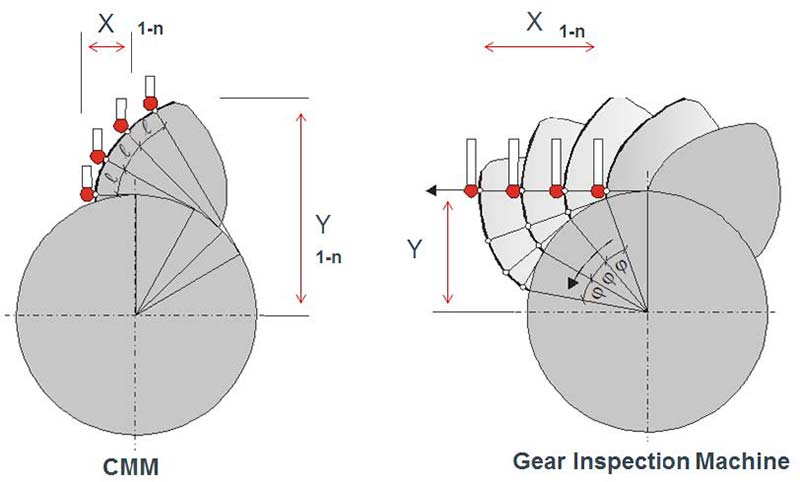
Gearing measuring centers as shown
in Figure 2 also have the advantage that
measured value recording takes place
for cylindrical gears with involute gearing
according to the generation principle
(Figure 4). The involute curve is generated
automatically through the coupled rotational
movement of the workpiece with
the tangential measuring axis, resulting in
stable measurement results, even in the
case of positional deviations of the probing
system due to environmental influences
in production, for example.
Figure 4 Measuring principle.
- Click image to enlarge
By contrast, profile measurement based
on polar coordinates, as is common in
general CMM, is significantly more sensitive
to positional variations.
Prerequisites for Reliable
Performance of Shop-Floor
Measurements
An important feature of shop-floor
measurement is that the operating staff
for the production equipment (hobbing
machines, grinding machines, etc.)
also carries out the gear measurements.
The purpose of the measurements is to
inspect gearing quality following a workpiece
change, for instance, or during
ongoing production.
This means that the measurements are
not carried out by trained measurement
technicians, but rather by machine operators.
Additional measures are therefore
required to perform reliable, accurate
measurements.
Figure 5 shows the layout of a shop
floor with an integrated measuring station.
There are production lines (PL1–
PLn) for the individual components of a
transmission. Each production line has
its own test station (QC1–QCn). Each
test station is also networked with a central
measuring chamber. In this central
measuring chamber, prototype measurements
are carried out, and the individual
measurement programs that will subsequently
be transferred to the test stations
in production are created. The measuring
results recorded on the shop floor are
then transferred back to the measuring
chamber, where approval will be granted
or additional evaluations, such as statistical
analyses, will be carried out.
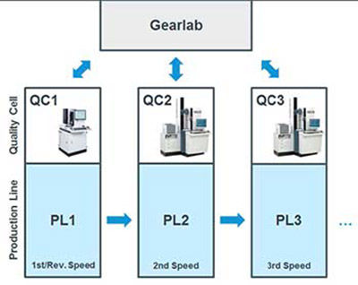
Figure 5 Layout of a gear component factory.
- Click image to enlarge
The objective is to enable the operator
to carry out the necessary measurements
on the shop-floor measuring machine
with as much ease and reliability as possible.
This relies in part on a simple, precise
workpiece fixture. A workpiece fixture
between centers lends itself well for shafttype
workpieces. For disk-shaped workpieces
and internal gearing, a chuck is the
fixture of choice. The chuck should be
designed so that few or no exchange parts
are required for different workpieces.
An automatic probe change rack on the
measuring devices is recommended when
using different probe elements for gearing
measurement. The probe change rack
enables all necessary probe elements to
be calibrated automatically at fixed intervals
(once per day or once per shift).
The individual measurement programs
are accessed by means of a simply
designed graphical user interface, as
shown in Figure 6. All measurement programs
needed for a measuring station or
specific transmission components can be
programmed into this page as on a desktop
and launched as necessary.
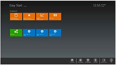
Figure 6 Software HMI.
- Click image to enlarge
The system also includes measurement
program retrieval via a barcode scanner.
As already mentioned at the out-set, workpiece cleanliness is important
for obtaining accurate, reliable measuring
results. The measuring station should
therefore also have a workpiece washing
station nearby. The advantage of a coldwater
washing station is that the workpieces
are not warmed, thus obviating temperature-
induced measurement variations.
Workpiece temperature is generally a
consideration for accurate measurements.
In gear measurement, certain measurement
parameters are insensitive to temperature,
while others respond with
greater sensitivity.
Due to the relatively small gearing
dimensions in the automotive industry,
temperature-induced changes in length
are relevant here only for certain parameters.
The relative test parameters for profile,
tooth trace, pitch and concentricity
measurements are rather insensitive.
Large, temperature-induced variations
can occur, however, when determining
tooth thickness or dimension over balls,
when the temperature of the workpieces
deviates from the reference temperature
of 68°F. In this case, a measuring device
with workpiece temperature probes is
used for compensation.
Maintenance and Calibration of
Shop-Floor Measuring Devices
Use of a measuring device on the shop
floor generally requires slightly more
maintenance and calibration.
Fixed procedures should therefore be
specified for individual measuring stations
as follows, for example:
Daily maintenance
- Inspection of traversing paths of measuring
device axes
- Monitoring of the device for unusual
noises during the measuring procedure
- Calibration of the probe elements used
(once per shift)
Weekly maintenance
- Inspection of the measuring device for
measuring accuracy by means of comparative
measurements against the reference
standard
- Compressed air supply check
- Cleaning of workpiece fixture components
Quarterly maintenance
- Replacement of filter elements in the
control cabinet
- Emptying of condensate from the compressed
air service unit
Annual maintenance
- Inspection of the measuring device by
an OEM service employee
As regards measuring accuracy, a comparative
measurement against a reference
standard across all measuring devices is
also needed at regular intervals.
Of course, the manner in which the
operating staff handles the measuring
device is an essential factor in maintenance
expenses and in ensuring consistent
measuring accuracy. It is certainly an
advantage if staff members receive basic
training in the proper handling of highprecision
measuring devices.
Summary
Quality monitoring of gearing workpieces
carried out on the shop floor offers a
number of benefits:
- Variations in measuring results are
identified more quickly, thereby reducing
the number of rejects.
- When changing tools on the machining
equipment, the operator can immediately
verify the settings by measuring
the workpiece and can make any necessary
corrections without lengthy production
breakdowns.
- The machine operator is thus directly
involved in the quality assurance process
and consequently performs with a
greater overall focus on quality.
- The number of complicated measuring
chambers can be reduced.
To successfully introduce quality assurance
on the shop floor, however, appropriate
prerequisites must be in place.
Careful planning is absolutely necessary.
Exchanges of experience with other
companies that have successfully introduced
this production structure can certainly
be helpful.
About Author
Dipl.-Ing. Günter
Mikoleizig currently
heads the Product
Management and
Application Engineering-
Department for gear
inspection machines at
the Klingelnberg GmbH,
Germany. For more than 30 years he is working
in the field of gear inspection technology and
he is well experienced with the design and
development of inspection machines and the
product management. He developed a product
line of inspection machines for all kind of gears
and other related parts with small dimensions
up to very big sizes. Mikoleizig presented
papers about gear inspection worldwide
and is also an active member of national and
international standardization committees.