A mapping is used to transform the rack coordinates (x,r, yr) to
polar gear tooth coordinates (uc, vc). This transformation can be
envisioned as wrapping a rack onto a pitch circle with the desired
pitch radius up. This transformation is the envelope of the rack as
it meshes with a circle of radius up. Depicted in Figure 5 is a rack
being wrapped onto a pitch circle with radius up.
Figure 5 Transforming or “wrapping” the rack onto the desired
pitch circle.
- Click image to enlarge
Cylindroidal Coordinates
A system of curvilinear coordinates is used to parameterize
the kinematic geometry of motion transmission between skew
axes. These curvilinear coordinates are based upon the cylindroid
determined by the two axes of rotation, $i and $o, and are
referred to as cylindroidal coordinates. Cylindroidal coordinates
consist of families of pitch, transverse, and axial surfaces. Pitch
surfaces are specified in terms of the axes of rotation $i and $o. $i
is the input axis (pinion) of rotation and $o is the output (ring)
axis of rotation. Pitch surfaces are a family of ruled surfaces, and
axodes are the unique pitch surfaces that depend upon a particular
I/O relationship. For this reason, the pitch surfaces are
referred to as the reference pitch surfaces.
A system of curvilinear coordinates (u, v, w) is used to
describe spiral bevel and hypoid gears. The coordinates (u, v, w)
used to parameterize these families of pitch, transverse, and
axial surfaces are formulated using the cylindroid defined by
the input and output axes of rotation. A design methodology
for spatial gearing analogous to cylindrical gearing begins with
the equivalence of friction cylinders. Figure 6 shows two such
wheels along with candidate generators. The I/O relationship g
defines which generator of the cylindroid is used to parameterize
the input and output friction wheels. These generalized friction
surfaces are two ruled surfaces determined by the instantaneous
generator. The transmission of motion between the
two generally disposed axes $i and $o via two friction surfaces
requires knowledge of the instantaneous generator. The location
of the instantaneous generator relative to the two axes $i and $o
depends upon:
- Distance E along the common perpendicular to axes of rotation
$i and $o
- Angle Σ between axes of rotation $i and $o
- Magnitude of the I/O relationship g
Figure 6 Two friction wheels for motion transmission between skew
axes.
- Click image to enlarge
Motion transmission between the two skew axes $i and $o
results in a combination of an angular displacement about the
instantaneous generator and a linear displacement along the
instantaneous generator. The ratio h of linear displacement to
that of the angular displacement is the pitch associated with
the instantaneous generator. The pitch hisa associated with the
instantaneous generator is the instantaneous screw axis, or ISA.
A transverse surface is an infinitesimally thin surface used to
parameterize conjugate surfaces for direct contact between two
axes. Candidate generators for the reference pitch surface are
determined by the generators of the cylindroid ($i; $o). Given g,
each position angular vi and axial position wi define a unique
point p in space. Allowing g to vary from -∞ to ∞, the point p
traces a curve in space. Another value of the input position vi
defines the same cylindroid. There is an angular displacement
between these two cylindroids. It is this two-parameter loci of
points p that compose the transverse surface. The Cartesian
coordinates r for the single point p on the generator $ai are:
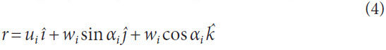
Rotating the above curve r about the zi-axis an amount vi
leads to:
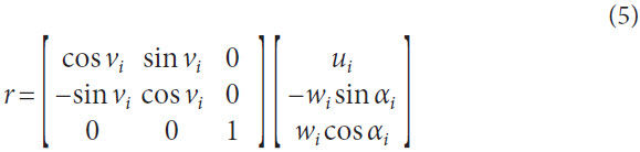
Where
u radius of hyperboloidal pitch surface (at throat)
v angular position of generator on pitch surface
w axial position along generator of pitch surface
α angle between generator and central axis of pitch surface
The axial surface provides the relationship between successive
transverse surfaces. For each value of vi, the axial surface
is the loci of generators determined by g, where -∞ < g < ∞. The
curves defined by holding two of the three parameters u, v, and
w constant are coordinate curves. Two parameters used to define a surface are the curvilinear coordinates
of that surface: the pitch surface by vi and
wi (ui = constant), the transverse surface by
ui and vi (wi = constant), and the axial surface
by ui and wi (vi = constant). Depicted
in Figure 7 are the pitch, transverse, and
axial surfaces determined using cylindroidal
coordinates (ui, vi, wi). Three surfaces
are used to describe the geometry of gear
elements.
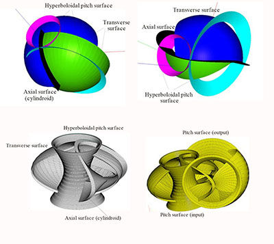
Figure 7 Pitch, transverse, and axial surface for uniform motion transmission..
- Click image to enlarge
The curvilinear coordinates (uc, vc, wc)
used to parameterize the proposed cutters
are defined by introducing a cutter-cylindroid
($ci; $co). This enables cutters to be
designed in pairs analogous to the design
of gear pairs where two cutters are proposed
for the fabrication of spiral toothed
bodies. One feature of the cutter cylindroid
is that expressions involving the cutters
are obtained by simply changing the
trailing subscripts in existing expressions
involving the input gear from “i” to “c”.
In order to minimize the notation necessary
to distinguish the input cutter from
the output cutter, only a “c” subscript is
used with no indication as to whether it
is the input cutter or the output cutter.
Implicit in the cutter designation will be an “o” subscript when
describing the input gear. Likewise, when describing the output
gear body, it will be assumed that associated with the cutter is an
“i” subscript to identify that it designates the input cutter. The
above reasoning is that two toothed bodies in mesh involve an
input and an output body. The three possibilities being:
- Input gear body and an output gear body
- Input gear body and an output cutter
- Input cutter and an output gear body
The two twist axes $ci and $co are the two screws of zero
pitch on the cutter cylindroid ($ci; $co). The generators $pc are
determined by also introducing a cutter I/O relationship gc.
Expressions for the radius uac and the angle αac are identical to
those for uai and αai, except E, Σ, and g are replaced by Ec, Σc, and
gc, respectively.
Hyperboloidal Cutter Coordinates
General hyperboloidal cutter elements are defined by introducing
a mapping within a system of cylindroidal coordinates.
The purpose of this mapping is to utilize knowledge of conjugate
curves for motion transmission between parallel axes and
apply it to conjugate surfaces for motion transmission between
skew axes. A visual representation of this mapping is shown in
Figure 8. There exists a single generator within a system of curvilinear
coordinates as part of the cylindroid ($i; $o) that is coincident
with each point (u, v). For an arbitrary axial position wc
along this generator, a transverse surface exists. Each value (u, v)
defines a different generator. The distance wc along each of these
generators from (u, v) to a single transverse surface is constant.
It is the image of these datum points (u, v) upon a given transverse
surface that defines the mapping. This mapping is valid for
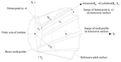
Figure 8 Mapping of planar gear profile onto transverse surface.
- Click image to enlarge
any type of cutter tooth profile (viz., involute, cyclodial, circulararc,
and convuloid).
The planar coordinates (u, v) used to define conjugate curves
are polar coordinates where v is an angular position about the
“z-axis” and u is the corresponding radius. Use of coordinates
(u, v) to specify conjugate curves in the plane are fashioned
such that conjugate surfaces in space are obtained using the cylindroidal
coordinates (uc, vc, wc). This is achieved by assigning
a value to the axial position wc and defining uc ≡ uc and vc ≡ v.
Cutter coordinates must be “scaled” to satisfy the appropriate
transverse pitches. Such scaling is illustrated in Figure 9 and is
obtained by recognizing that the virtual length of the striction
curve spc is the component of its length perpendicular to the
tooth. This scaling is performed prior to the “wrapping” of the
rack onto the circular disk depicted in Figure 3 and depends on
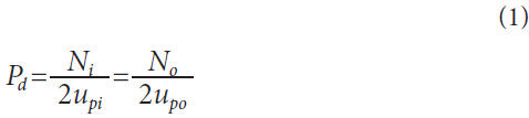
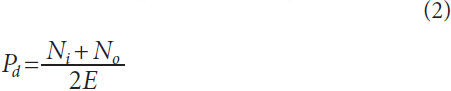
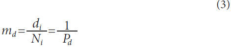
the diametral pitch. The diametral pitch Pd used to parameterize
the cutter teeth depends on the size or radius of the input and
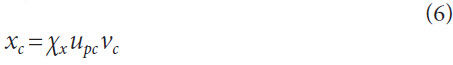
output cutter. The x-scaling or stretch along the x-axis is shown
in Figure 9 and depends on the cone angle αpc; thus, for an arbitrary
angle vc, the corresponding parameter xr used to evaluate
the expressions for the tooth profile becomes:
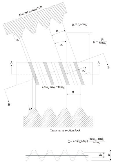
Figure 9 Scaling of tooth profile on cutter element.
- Click image to enlarge
Where
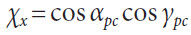
The angle apc = ypc at the throat (i.e., wc = 0). It is the diametral
pitch at the throat that is used to specify the pitch of the cutter
profiles. The cutter is expressed using the Cartesian coordinates
(xc, yc, zc) as follows:
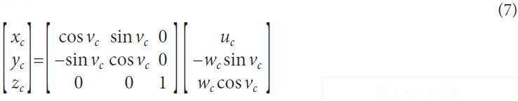
The image of the coordinates
(xc, yc, zc) upon the transverse surfaces
must account for the cutter spiral.
Consequently, a transverse angular
displacement Δvѱc is superimposed
on the mapping as follows:
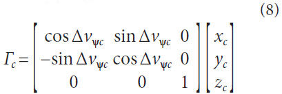
The cutter spiral depends on the ratio between the axial displacement
Δwѱc and the angular displacement Δvѱc. The displacement
Δvѱc is based on a constant lead for a given transverse
surface and the spiral angles ѱc for each radii uc are different.
Note that the displacement Δvѱc is based on the lead for the reference
pitch surface and the spiral angles ѱc change for each
radius uc.
Illustrative Example
This example presents a spiral hypoid gear set for motion transmission
between skew axes using Delgear software (Ref. 16).
The shaft angle is 90° and the shaft offset is 25 mm. The speed
ratio 3.27; 11 teeth on the pinion and 36 teeth on the ring gear.
The face width is 35 mm, the axial contact ratio is 3.0 and the
nominal spiral angle is 61°. The tooth profile is a standard invo-
Figure 11 Input and output gears with involute teeth.
Figure 10 Rack, transverse profile, hyperboloidal cutter.
Figure 9 Scaling of tooth profile on cutter element.
60 GEAR TECHNOLOGY | May 2015
[www.geartechnology.com]
technical
lute tooth profile. The normal pressure angle is 20°, the transverse
contact ratio is 1.25, the addendum constant is 1.0 and the
dedendum constant is 1.2. The variable diameter cutter has three
teeth and the nominal lead angle is 10°. Figure 10 shows the rack
tooth, a transverse segment of the cutter, and a virtual model of
the cutter. The gear pair is depicted in mesh in Figure 11.
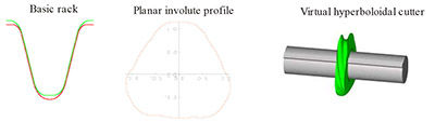
Figure 10 Rack, transverse profile, hyperboloidal cutter.
- Click image to enlarge
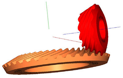
Figure 11 Input and output gears with involute teeth.
- Click image to enlarge
Summary
Demonstrated is the specification of involute gear teeth on hypoid
gears. This process involves the specification of a classical
involute rack, a mapping that transforms this rack to a planar
circular profile. A system of cylindroidal coordinates is used to
define hyperboloidal cutters. Another transformation is used
to map the planar circular profile to a hyperboloidal cutter with
suitable geometry for specifying general spiral bevel and hypoid
gear pairs. An example of an automotive rear differential gear
set is presented to illustrate the process.
- Shtipelman, B.A. Design and manufacture of Hypoid Gears, 1978, John Wiley
& Sons, New York.
- Stadtfeld, H.J. Handbook of Bevel and Hypoid Gears, 1993, Rochester Institute
of Technology, Rochester.
- Litvin, F.L. and A. Fuentes. Gear Geometry and Applied Theory, 2004, 2nd
Ed. Cambridge University Press, London England.
- Wu, D. and J. Luo. A Geometric Theory of Conjugate Tooth Surfaces, 1992,
World Scientific, New Jersey.
- Wang, K.L. and S.K. Ghosh. Advanced Theories of Hypoid Gears, 1994,
Elsevier, Amsterdam.
- Radzevich, S. P. Theory of Gearing: Kinematics, Geometry, and Synthesis,
2012, CRC Press, Taylor and Francis Group.
- Kapelevich, A.L. Direct Gear Design, 2013, CRC Press, Taylor and Francis
Group.
- Xiao, D.Z. and A.T. Yang. “Kinematics of Three-Dimensional Gearing,” 1989,
Mechanism and Machine Theory, Vol. 24, Issue 4, pp. 245-255.
- Figliolini, G., H. Stachel and J. Angeles. “The Computational Fundamentals
of Spatial Cycloidal Gearing,” 2009 Proceedings of 5th International Workshop
on Computational Kinematics, Dusseldorf Germany, May, pp. 375-384,
Springer.
- Hestenes, D. “Old Wine in New Bottles: a New Algebraic Framework for
Computational Geometry,” 2001, Geometric Algebra with Applications in
Science and Engineering, E. Bayro-Corrochano and G. Sobcyzk, Eds. pp.
1-16, Birkhauser, Boston, MA.
- Ito, N. and K. Takahashi. “Extension of the Euler-Savary Equation to
Hypoid Gears,” 1999, MSME Mechanical Systems, Machine Elements, and
Manufacturing, Series C, Vol. 42, No. 1.
- Grill, J. “Calculating and Optimizing of Grinding Wheels for Manufacturing
Grounded Gear Hobs,” 1999, 4th World Congress on Gearing and Power
Transmission, Paris France, Mar. 16-18, pp. 1661-1671.
- Baozhen, L., H. Lowe and W. Xumwei. “A New Approach to the Theory
of Gearing Using Modern Differential Geometry,” 2013, International
Conference on Gears, Munich Germany, Oct. 7-9, pp. 1379-1390.
- Phillips, J.R. Geared Spatial Involute Gearing, 2003, Springer, Berlin.
- Dooner, D.B. Kinematic Geometry of Gearing, 2012, 2nd Ed., Wiley, London.
- http:\\www.delgear.com.
This paper was originally presented at the 2014 International Gear Conference, Lyon Villeurbanne, France. It is republished here with the author’s permission.
About Author
David Dooner graduated from the University of Florida
in 1991. Afterwards, he was a visiting scientist with the
Russian Academy of Sciences in Moscow and joined
the University of Puerto Rico-Mayaguez (UPRM) in 1994.
Since joining UPRM, he has been involved with teaching,
services, and research. His research focus involves a
mathematical approach for the design and manufacture
of general hypoid gear pairs. He currently teaches
mechanism design, machine design, and senior capstone design. He is
currently a member ASME, ASEE, and AGMA.


 Figure 1 Face cutting.
 Figure 2 Conical segments for hypoid gears.