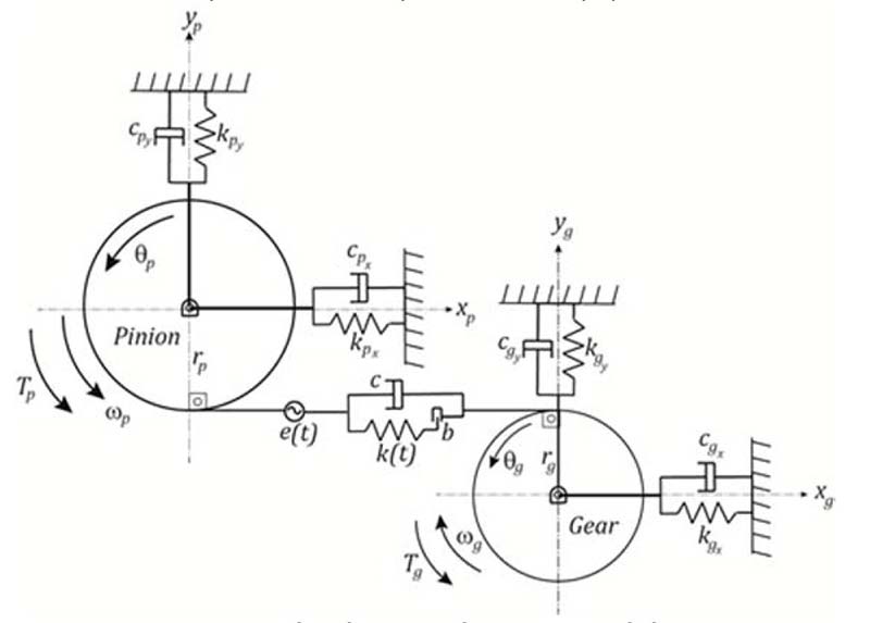
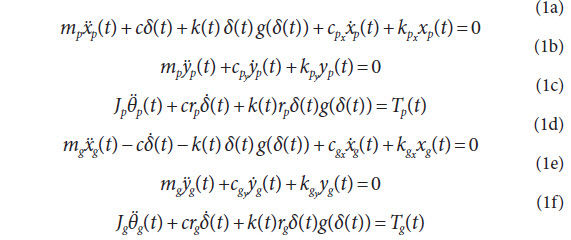
and gear mesh contact loss is mathematically induced by the
unit step function, g(δ(t)). The unit step function, g(δ(t)) = 0,
if δ(t) < 0 and g(δ(t)) = 1, if δ(t) ≥ 0. An over-dot means a time
derivative of the corresponding variable in the equations of
motion. In Equation 2 e(t) is the time-varying transmission
error function that represents the motion errors caused by
gear mesh deflections due to load and also due to manufacturing
deviations. Transmission error is a periodic function and
is simulated via discrete Fourier series amplitude and phase
of this periodic function in modeling schemes that exist in literature
(Refs. 16–17). The model can employ the transmission
error function either in a time-series form or in a broad-band frequency domain form from a measured or a simulated timeseries.
In other words, this model makes it possible to use measured
time-domain or broad-band frequency domain representation
of the long-period quasi-static transmission error to
predict dynamic transmission errors and dynamic mesh forces.
Moreover, the dynamic model developed in this study accepts
measured transmission error signal with any resolution, automatically
synchronizing the time resolution of the transmission
error signal with the time resolution of the dynamic model
equations for the right solution. A simplified mathematical representation
of such a signal in the time domain can be given as:
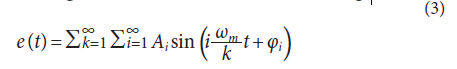
This transmission error function assumes an infinite number
of harmonics, sub-harmonics and overtones of the mesh frequency
ωm that are superimposed to obtain a broadband transmission
error function as in Equation 3. The quasi-static transmission
error, e(t), when measured from a gear set with indexing
errors, is periodic over the complete rotation of the gears in
mesh if the gears are unity-ratio gears. If two gears with different
number of teeth are used, then transmission error signal is
periodic over Z1Z2 rotations of both gears, where Z1 and Z2 represent
the number of teeth on the pinion and the gear, respectively.
On the contrary, for a gear set with no indexing errors,
transmission error is periodic over a mesh cycle and over a complete
rotation of the gear. This difference constitutes the main
mechanism for the signals to convolute.
This dynamic model employs a number of assumptions. First
of all, gear wheels are assumed to be rigid, with flexibility only
coming from the gear mesh. Gear motions in some other directions,
such as rotations about x and y, and translations in z, are
excluded for the sake of simplicity. Bearings are assumed to be
linear. Finally, simplified damping elements are used. The model
presented here makes use of Rayleigh damping, where [C] = α
[M] + β [K]. Here, [C], [M] and [K] represent the overall system
damping, mass and stiffness matrices and αand β are constant
coefficients, and α = 479 and β = 1.4·10-7 was used here.
Experimental Transmission Error Measurements
Test machine and set-up. In this study, an open-architecture
gearbox with drive and load capacity was used to measure the
quasi-static transmission error of spur gears with different
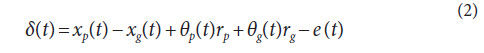
indexing errors. This rig (Fig. 2) is designed to operate gears
under high-load and low-speed (loaded quasi-static) conditions.
A small DC motor is connected to a 100:1 ratio harmonic drive
to reduce the speed significantly while increasing the torque
delivered to the gear pair. The harmonic drive was directly
connected to a torque-meter to monitor the input torque provided
to the gearbox. The output side of the torque-meter was
connected to one of the test gear shafts via a flexible elastomer
coupling. The test gearbox consisted of a unity-ratio spur
gear pair held by relatively rigid
shafts. Concentric bearing housings
holding the bearings were
mounted on two massive split
pedestals. The shaft of the driven
(output) gear was connected
to a magnetic particle brake with a maximum torque capacity of
400 Nm by means of another flexible coupling. The shafting permitted
optical rotary encoders to be mounted on their free ends
outside the bearing pedestal for measurement of TE. The rotary
encoders (Heidenhain, RON 287) have the capability to measure
18,000 positions per complete rotation.
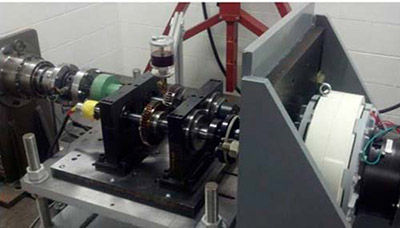
Figure 2 Quasi-static transmission error (TE) measurement set-up.
- Click image to enlarge
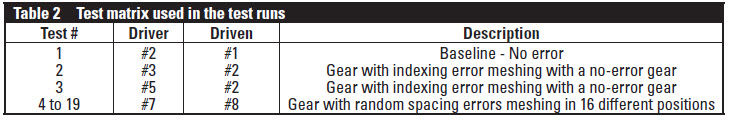
Test specimens and test matrix. Unity-ratio spur gear pairs
were used in this study with an operating center distance of
150 mm. A total of 7 gears with tightly controlled indexing
errors formed the inventory for the test matrix. Two gears with
no indexing errors, three test gears with discrete spacing errors
at a few teeth along with two additional gears with randomized
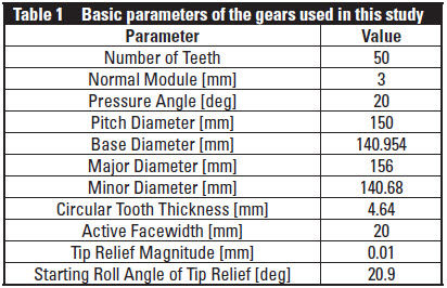
spacing errors were procured specifically for this study. Basic
gear parameters for these gears are listed in Table 1. Each gear
pair had a theoretical contact ratio of 1.8. The test gears had the
following intentional spacing errors:
- Gears #1, #2: Gears with no indexing errors (in reality, errors
exist but less than 2 μm).
- Gear #3: Gear with a single tooth having a negative 15 μm
spacing error.
- Gear #4: Gear with two consecutive teeth having negative
15 μm spacing errors.
- Gear #5: Gear with two teeth having negative 15 μm indexing
errors with the tooth in between them in the correct position.
- Gears #6, #7: Gears with all teeth having spacing errors with
randomly distributed magnitudes between the range [-15,
15] μm.
Each error was placed in the negative direction, which refers
to the tooth entering mesh later than expected. The negative
direction of the errors was chosen because they were obtained
by removing additional material from the teeth with no error.
Likewise, if a tooth enters mesh earlier than nominal compared
to the previous tooth, the spacing error is positive. Moreover,
a more realistic case where two gears having various different
indexing errors was studied utilizing the gears designated as
Gears #6 and #7. These gears were machined to have random
spacing errors within the range [-15, 15] μm. Furthermore, with
right and left flanks having different error values, these two gears
represented four different random spacing error conditions.
Transmission error measurements. The transmission error
measurement system used two separate encoders to determine
the angular position of each gear shaft. The signals from the
encoders were passed into encoder conditioners. A commercially
available transmission error measurement system was
used to process the conditioned encoder signals to compute the
transmission error. The software has high and low pass filtered
TE time histories of the same data to quantify shaft and mesh
frequency content of the TE signal. This system considers either
the driving pinion (input) encoder or the driven gear (output)
encoder as the reference signal to determine output and input
TE signals (both in μrad), or as a linear displacement along the
line of action as:
These TE measurements are processed using data segments
corresponding to 16 complete gear rotations. In Figure 3 a
representative measured loaded e(t) is presented from Test #2
at 200 Nm. In Figure 3 (a, b), the unfiltered (raw) and the
high-pass filtered versions of the measured e(t) is presented.
Although the measurements were recorded for 16 complete gear
rotations, only one complete rotation, including 50 gear mesh
cycles, is presented in these figures. These representative measurements
clearly exhibit the intentional indexing error amount
generated on the test gears. With the gear rotational speed of
10 rpm, gear mesh frequency is 8.33 Hz. Accordingly, the measured
TE signal is put through a high-pass filter with a cut-off
frequency slightly higher than 0.167 Hz, removing frequencies
equivalent to one shaft order frequency and below. A family
of baseline tests of the two no-error gears was run first at all
of the operating conditions specified. The sinusoidal waviness
in Figure 3(a) is the once-per-revolution amplitude caused by
the pitch line run-out error of the gear pair. Once such low-frequency
content is removed by the high-pass filter, the remaining
TE is seen to be dominated by the gear mesh orders (50, 100,
150, etc.), and the resultant TE time histories reveal mesh frequency
components of TE. It is also observed from the filtered
data that certain tooth-to-tooth variations exist. This is a direct
result of a small amount of spacing errors present in these noerror
gears — despite all efforts to minimize them. As a result,
the frequency spectrum has other non-zero, non-mesh harmonics
— especially below the fundamental gear mesh order of 50.
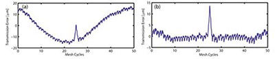
Figure 3 Measured static TE from Test #2: (a) unfiltered TE; (b) filtered TE.
- Click image to enlarge
Results and Discussion
In this section, impact of indexing errors on dynamic response
of gear pairs is presented utilizing predicted dynamic transmission
error time histories and corresponding frequency spectra.
Dynamic transmission error (DTE) predictions are compared to
the baseline measured quasi-static transmission error e(t) time
histories (STE) and frequency spectra of the corresponding gear
pairs. Here results are reported in terms of dynamic transmission
error, as it provides the most direct physical link between
the measured STE and predicted DTE while the model is also
capable of predicting dynamic mesh force, dynamic bearing
forces and displacements and gear motions, as defined in all 6
degrees of freedom.
First, a linear time-invariant (LTI) version of the same
dynamic model was run to determine the resonant frequencies
and corresponding mode shapes of the baseline gear pair with
no indexing errors. The resonant frequencies were found to be
at 3,370, 5,940 and 7,300 rpm. As pointed out earlier, dynamics
regarding the y-direction motions were excluded from the
discussion, as they can be treated independently. Later, dynamic
response and mesh force spectra of the same baseline gear
pair were predicted utilizing both LTI and NTV versions of the
model to identify the off-resonant speed (frequency) ranges of
the system within which specific frequencies were chosen for
further analysis. The off-resonant frequencies that were used for
further analysis are 400 rpm, 1,300 rpm and 2,100 rpm. At these
off-resonance speeds, magnification on the TE due to the gear
pair dynamics can be clearly observed without the extra amplifications
due to mesh resonances and nonlinear effects.
Although numerous test cases, along with the corresponding
dynamic model predictions, were carried out, a subset of the
results is reported here to illustrate the importance of incorporating
indexing errors into the gear design and dynamics considerations.
Results from Test #1 that included the baseline gears
with no indexing errors along with the corresponding dynamic
transmission error predictions are shown in Figure 4.
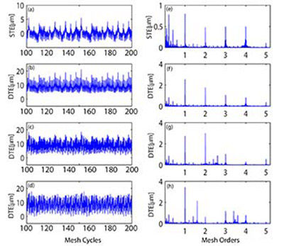
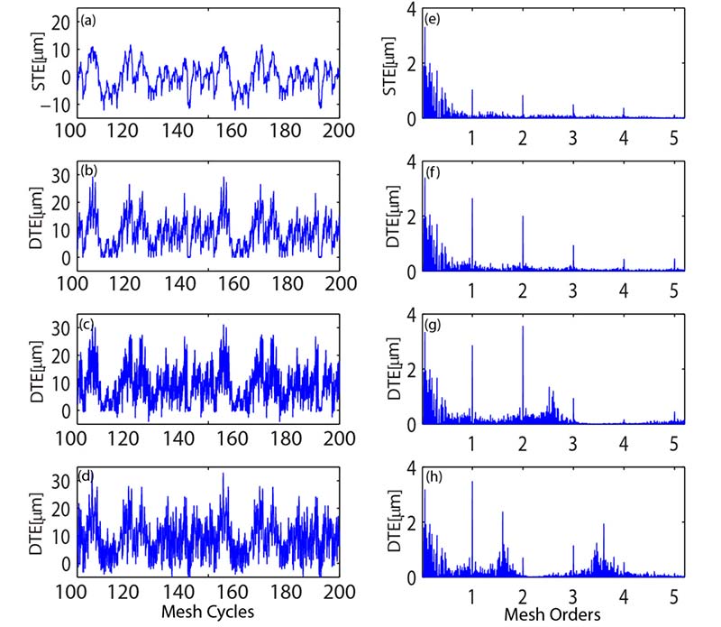
Figure 4 Measured static TE (a) along with predicted dynamic TE time histories from Test#1 at 400,
1,300 and 2,100 rpm (b-d); and corresponding frequency spectra (e-h).
- Click image to enlarge
In Figure 4(a) a measured STE time history is given between
gear mesh cycles 100 to 200. This mesh cycle range was
intentionally chosen to exclude any transient effects taking
place — especially for the initial cycles for the predicted DTE.
In addition, measured STE and predicted DTE traces were presented within the same mesh cycle
ranges to clearly demonstrate the
dynamic magnification effects. It is
apparent from both Figure 4(a), and
its corresponding frequency spectrum
Figure 4(e), that even baseline
gears had limited indexing errors
on them along with teeth deflection
and other geometric imperfections
that contributed to the
STE. Predicted DTE at 400 rpm,
1,300 rpm and 2,100 rpm is presented
in Figure 4(b-d), along with their
corresponding frequency spectra
in Figure 4(f-h). Although it is
clearly observed from the comparison
between time histories for STE
and DTE at different speeds how
dynamics play a significant role on
TE, note also that frequency spectra
are intentionally presented in
gear mesh orders to help us detect
the changes at main mesh order and
its harmonics, shaft orders and also
gear pair resonances at once. For
instance, in Figure 4(g), when gears
were rotating at 1,300 rpm, resonant
peak revealed at the mesh order 2.8
that corresponded to the second
mode (torsional mode) of the system.
Similarly, in Figure 4(h), when
gears were rotating at 2,100 rpm,
resonant peaks at the mesh orders
1.6 (torsional mode) and 3.6 (coupled
torsional-translational mode)
were revealed due to gear pair
dynamics.
In Figure 5 STE and DTE time
histories, and corresponding frequency
spectra from Test #2, are
given following the same sequence
in Figure 4. Test #2 included a gear
with no indexing errors and a pinion
with an intentional spacing error
of 15 μm at tooth #25 (Fig. 3). The
peaks that are seen in the filtered
STE time trace (Fig. 5(a)) exhibit
how the discrete spacing error
of the particular tooth on the gear
comes in mesh and causes a sudden
increase in the measured STE once
during a complete rotation of the
gear; i.e. — once in every 50 mesh
cycles. The fact that one of the teeth
has discrete spacing error, whereas
all the other teeth have almost perfect
spacing, breaks the cyclo-symmetricity
of the meshing action and thus mistunes the dynamics of the gear
pair. This can essentially be observed in
Figure 5(a-d), when the same gear pair
was used but was run at sequentially
increasing speeds. Especially, in Figure
5(c) and (d), when the gears were rotating
at 1,300 and 2,100 rpm, respectively,
time traces exhibit how more than once
mesh cycle was affected due to a single
discrete spacing error on the gear.
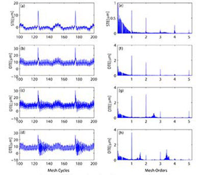
Figure 5 Measured static TE (a) along with predicted dynamic TE time histories from Test #2 at
400, 1,300 and 2,100 rpm (b-d); and corresponding frequency spectra (e-h).
- Click image to enlarge
Under dynamic conditions, teeth
do not only deflect due to the applied
external load, but also oscillate about
this pre-deflected position under the
influence of dynamic loads. Moreover,
indexing errors cause time and phase
lags (or leads) on the mesh timing that
can cause dynamic loads to become
magnified and also modify them to
where they become more impulsive.
Gear contact ratio reinvigorates the gear
pair dynamics as it is the most important
design parameter that decides upon
when and how much load will a particular
tooth carry. Moreover, mesh damping
strongly influences the dynamic
response of the gears, but is hard
to determine and also to change. The
other important point to stress here is
the energized broad-band shaft order
regime and its physical reasoning. In
Figure 5(e-h), although run-out effects
were excluded from the measured STE,
shaft order (orders lower than the fundamental
mesh order) peaks and integer
multiples are revealed. The main
reason is that the teeth with deterministic
spacing error repeats and leaves its
signature once in every rotation of the
gear, leaving a strong mark on the frequency
spectrum. This effect becomes
even more significant when dynamics
come into play at higher speeds. The
peaks revealed at integer multiples of
the shaft orders are due to the amplitude
and phase modulation of the TE
and will be further studied in a subsequent
study by the authors. In Figure
6, results from Test #3, where an intentional
deterministic indexing error pattern
of 0-15-0-15-0 μm was used on the
pinion, is presented. In this case there is
a single, intentionally misplaced tooth
on the gear that was followed by both
a perfectly positioned and misplaced
tooth. This error pattern introduced
another layer of complications to the
resulting frequency spectra by strengthening 2× shaft orders along with 1× shaft orders. The complicated
phasing relationship affected the resulting peak distribution
in the frequency spectra, which is more clearly visible from
orders lower than the fundamental (1×) gear mesh order.
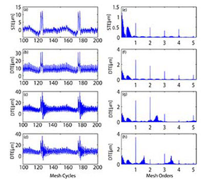
Figure 6 Measured static TE (a) along with predicted dynamic TE time histories from Test #3 at
400, 1,300 and 2,100 rpm (b-d); and corresponding frequency spectra (e-h).
- Click image to enlarge
The measured STE and predicted DTE thus far have included
intentionally created, deterministic indexing errors on the gear.
In Figure 7, however, results from Test #4, which included random
spacing errors on the pinion, are presented. The random
error pattern is definitely more representative of the real indexing
error patterns observed on the gears manufactured using
cutting, shaping etc. operations. Although randomly distributed,
spacing errors were kept between the range [-15, 15] μm.
As seen both from the time traces and the corresponding spectra
(Fig. 7), random spacing error patterns cause a truly broadband
excitation, thereby activating the resonant peaks and shaft
orders — regardless of gear speeds.
Conclusions

Figure 7 Measured static TE (a) along with predicted dynamic TE time histories from Test #4 at 400,
1,300 and 2,100 rpm (b-d); and corresponding frequency spectra (e-h)
- Click image to enlarge
In this study a model to predict gear pair dynamics using measured,
long-period quasi-static transmission error of a gear pair
was developed. This model uses measured, broadband static TE
excitation with any time and frequency resolution and predicts
dynamic gear mesh force, dynamic TE and bearing forces. Both
time domain and frequency domain results can be obtained at
steady-state and transient speed conditions. First, gears were
intentionally mistuned through tightly-controlled deterministic
and stochastic indexing errors, and resulting gear pair dynamics
were compared against a baseline gear pair with no indexing
errors (minimized, but not zero). Cases with gears having
limited, discrete indexing errors increase the dynamic response
during a limited number of mesh cycles, thus increasing the
dynamic response. Their frequency spectra are enriched by
additional shaft order peaks due to amplitude and frequency
modulations caused by the perturbed transmission error excitation.
Cases with random indexing error exhibit even greater
broadband response, having peaks at shaft order and its integer
multiples along with mesh order and its harmonics. They
exhibit significantly more energy content at frequencies lower
than the fundamental mesh frequency. The broader spectrum
is caused by the broadband TE excitation causing a frequency
modulated dynamic mesh force spectrum.
References
- AGMA Technical Standards. ANSI/AGMA 2015-1-A01.
- Remmers, E.P. “Gear Mesh Excitation Spectra for Arbitrary Tooth Spacing
Errors, Load and Design Contact Ratio,” J. of Mech. Des.100, 1978, 715–722.
- Mark, W.D. “Analysis of the Vibratory Excitation of Gear Systems, Part I:
Basic Theory,” J. Acoust. Soc. Am. 63 (5), 1978, 1409–1430.
- Mark, W.D. “Analysis of the Vibratory Excitation of Gear Systems, Part II:
Tooth Error Representations, Approximations, and Application,” J. Acoust.
Soc. Am. 66 (6), 1979, 1758–1787.
- Kohler, H. and R. Regan. “The Derivation of Gear Transmission Error from
Pitch Error Records,” J. Mech. Eng. Science, 199 (C3), 1985, 195–201.
- Mark, W.D. “The Role of the Discrete Fourier Transform in the Contribution
to Gear Transmission Error Spectra from Tooth Spacing Errors,” J. Mech.
Eng. Science, 201(C3), 1987, 227–229.
- Kohler, H., R. Regan and W. D. Mark. “The Derivation of Gear Transmission
Error from Pitch Error Records,” Discussion, J. Mech. Eng. Science, 201(C3),
1987, 230–232.
- Padmasolala, G., H. H. Lin and F. B. Oswald. “Influence of Tooth Spacing
Error on Gears With and Without Profile Modifications,” NASA/TM 2000-
210061 PTG-14436, October 2000.
- Wijaya, H. “Effect of Spacing Errors and Runout on Transverse Load Sharing
and Dynamic Factors and Idler Gear Dynamic Analysis,” MS Thesis, The
Ohio State University, Columbus, Ohio, 2001.
- Spitas, C. and V. Spitas. “Calculation of Overloads Induced by Indexing
Errors in Spur Gearboxes Using Multi-Degree-of-Freedom Dynamical
Simulation,” J. Multi-Body Dynamics 220, 2006, 273–282.
- Milliren, M. “An Experimental Investigation Into the Various Errors on the
Transmission Error and Root Stresses of Spur Gears,” MS Thesis, The Ohio
State University, Ohio, 2011.
- Handschuh, M. An Investigation into the Impact of Random Spacing Errors
on Static Transmission Error and Root Stresses of Spur Gear Pairs,” MS
Thesis, The Ohio State University, Ohio, 2013.
- Tamminnana, V.K., A. Kahraman and S. Vijayakar. “On the Relationship
between the Dynamic Factors and Dynamic Transmission Error of Spur
Gear Pairs,” J. Mech. Des., 129, 2007, 75–84.
- Kahraman, A., J. Lim and H. Ding. “A Dynamic Model of a Spur Gear Pair
with Friction,” 12th IFToMM World Congress, Besançon (France), June
18–21, 2007.
- Blankenship, G. W. and A. Kahraman. “Steady State Forced Response of a
Mechanical Oscillator with Combined Parametric Excitation and Clearance
Type Nonlinearity,” J.Sound and Vibr., 185, 1995, 743–765.
- Windows LDP. The Ohio State University, Columbus, Ohio, 2013.
- External2D. Advanced Numerical Solutions, Inc., Hilliard, Ohio, 2013.
About Author
Dr. Murat Inalpolat is an
Assistant Professor in the
Department of Mechanical
Engineering at The University
of Massachusetts Lowell. He
has more than a decade of
experience in the areas of
structural health monitoring;
damage detection/diagnostics and prognostics;
structural dynamics and acoustics; and signal
processing — along with rotating machinery
dynamics and noise. His most current research
focuses on structural health monitoring,
diagnostics, prognostics, and operational
damage detection and identification. He also
has extensive project experience working on
aircraft- and rotorcraft-related projects obtained
while working at the General Electric Global
Research Center. He has been a reviewer
for such publications as the Journal of Sound
and Vibration; Mechanical Systems and Signal
Processing; and ASME Journal of Mechanical
Design. Inalpolat was previously awarded by CTI
(Car Training Institute of Germany) the prestigious
“Young Drive Experts” award based on his quality
of the research
Michael J. Handschuh
is a PhD student in the
Mechanical and Aerospace
Department of The Ohio State
University, having received
his BS and MS degrees in
Mechanical Engineering in
2011 and 2013, respectively.
Handschuh is a Graduate Research Associate
with the Gear and Power Transmission Research
Laboratory.
Ahmet Kahraman is
Howard D. Winbigler
Professor of Mechanical
and Aerospace Engineering
at the Ohio State University.
He is the Director of Gleason
Gear and Power Transmission
Research Laboratory. He also
directs the Pratt & Whitney Center of Excellence
in Gearbox Technology.