Suitable for incorporation into production, the machine is able to achieve 100 percent inspection of tasks, such as identifying the so-called “ghost orders” that represent the major contribution to gear noise in most cases.
While the single flank test is run at a lower speed of 30 rpm, a torsional acceleration test is also performed with measurements taken at high speeds of 500–3000 rpm, at a constant speed/constant torque, at constant speed/ramp torque and at ramp speed/constant torque.
The signal of the sensor is elaborated to obtain a fast Fourier transform (FFT) that shows the amplitude of the frequencies of vibrations, identifying the contribution during different stages. The angular TE (Transmission Error) values are converted into linear data.
The Fourier analysis can be used to understand the possible root causes contributing to the nonconformity of the noisy gear. The type of peaks detected over the FFT spectrum of the gear may have different origins, but all of them are related to the manufacturing process. For example, it might be due to an offset (misalignment) that occurred to the grinding wheel, generating eccentricity. In other cases, it may indicate local pitch errors or profile errors due to a division error on the machine tool, or a nonconformity could occur due to an unbalanced grinder or from the vibration of the grinding tool.
Retrieving this type of information can be vital to correctly provide feedback to the manufacturing process to ensure the quality of the gear product.
Manufacturers that decide not to adopt an individual NVH gear tester must cope with the concrete possibility of getting a higher number of scraps and noisy gearboxes, without comprehending the real reason for the nonconformity. If a gearbox fails the end-of-line test once it is completely assembled and, consequently, one or more gears are suspected as being the source of the error, then this is often followed by a manual disassembly, the replacement of each gear and the performance of a new measurement of those gears in the laboratory. It appears clear that this approach is time-consuming and far from cost-effective. Other than that, as was stated earlier, is that even remeasuring the gear (with a traditional gear measuring Instrument) might not ensure the identification of the failure. As a matter of fact, a “perfect” gear may still be the cause of any gearbox noise.
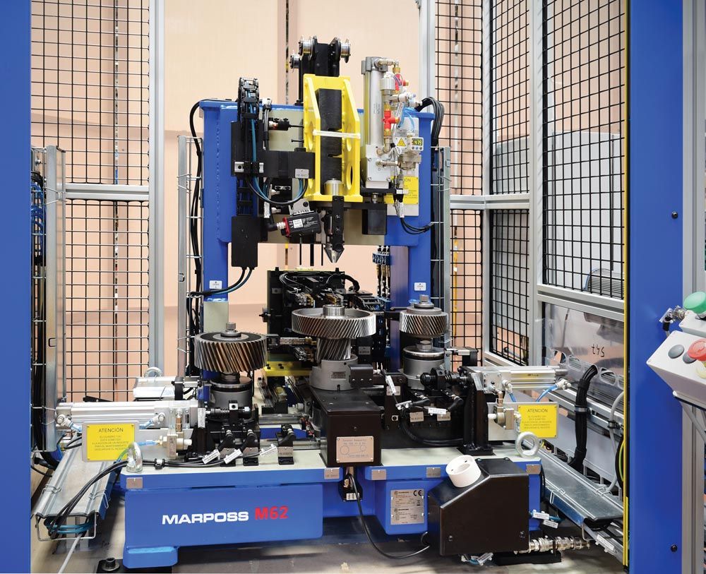
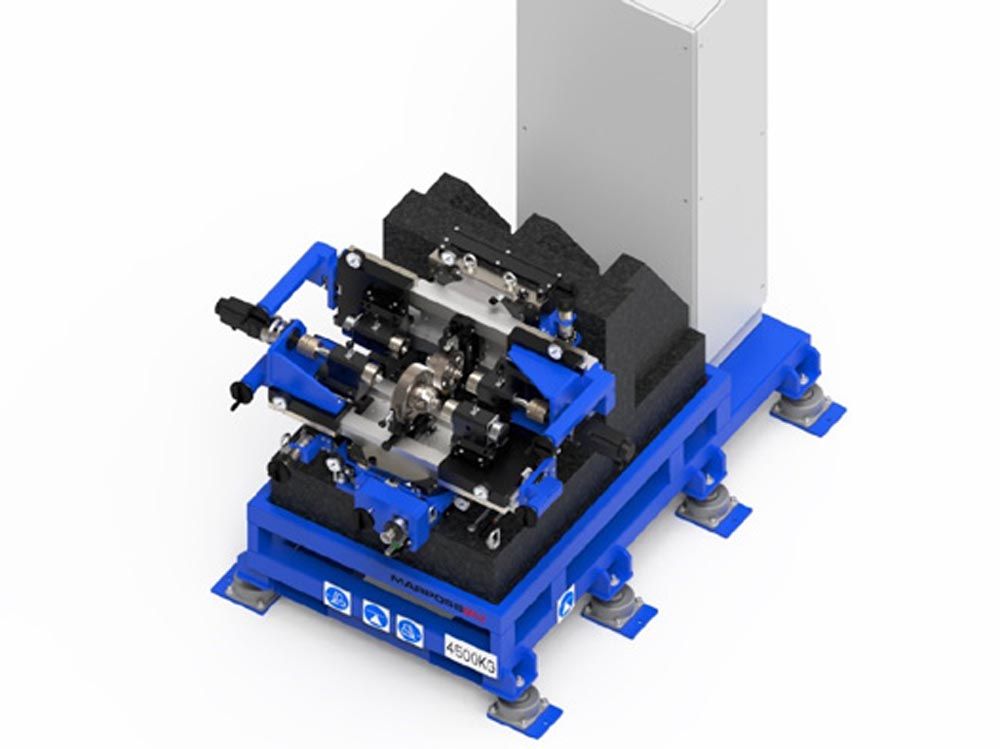
Figure 3—In addition to single flank testing, a torsional acceleration test can also be performed, helping to identify defects that might otherwise only be revealed once the gearbox is assembled.
The NVH G-EAR tester was developed for gear testing with a specific focus on EV applications, but it is really an evolution of well-known and established technology. The real achievement in gear quality control is the use of noncontact technology for measuring and inspecting gears on the shop floor.
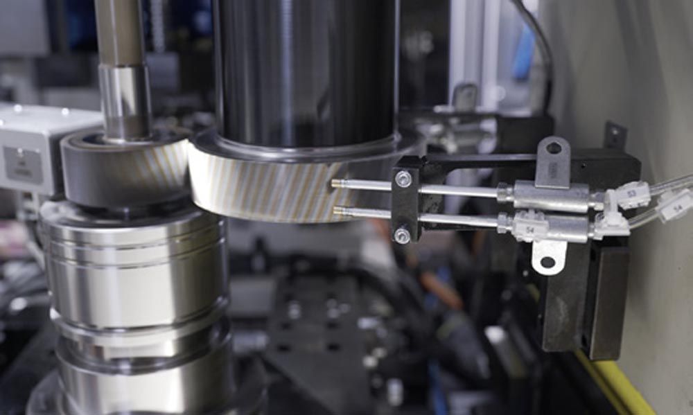 Figure 4—Identifying potential gear defects at the component level is crucial to eliminating transmission noise.
In this respect, Marposs has recently introduced another system that uses laser profile sensors and the optical triangulation principle. As compared to dedicated gear gauging systems or gear laboratory machines, the use of laser technology enables the system to easily adapt to inspecting a variety of gear sizes and shapes in a very short time. The cycle time, in fact, is key. And being fast does not normally match with accuracy.
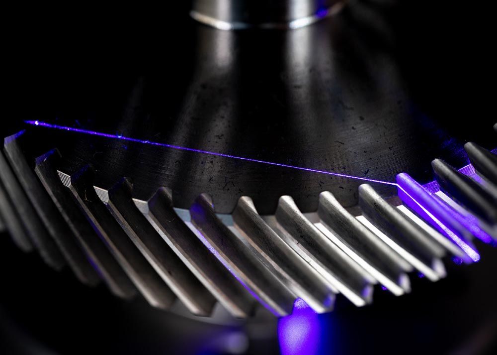 Figure 5—The application of noncontact technology—such as lasers and cameras—is also evolving to tackle the increased need for gear measuring in e-drives.
We previously mentioned that profile and lead characteristics have reached tighter tolerances in gears for electric vehicles, forcing gear producers to seek solutions to keep those parameters under control while still achieving production rates. That is where the noncontact technology applies best.
The laser profilers project a laser line on the gear at a specific angle, collecting data to generate the entire Z-X profile through an image sensor placed behind the optical receiver. The gear is then quickly rotated 360 degrees to collect data points from movement along the Y axis, which is combined with the Z-X profile to create a complete 3D reconstruction and representation of the part in less than a minute, made possible through specific software algorithms. The system then executes the requested measurement and inspection tasks. Line operators can easily review images and navigate to the desired level of detail to identify any anomalies.
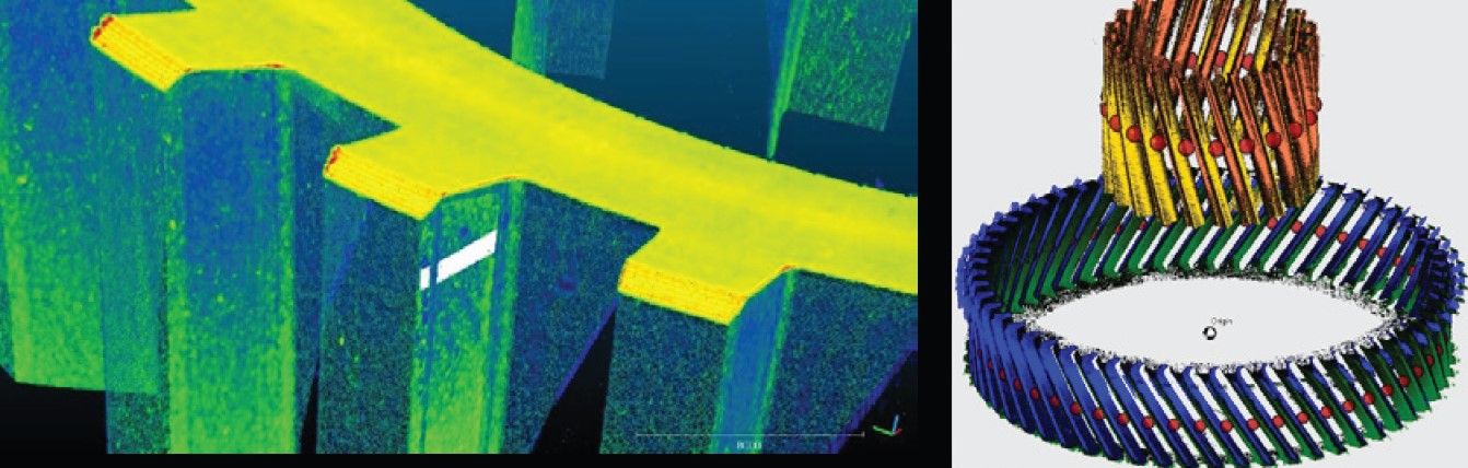
Figure 6—In Marposs’ newest system laser profile sensors and the optical triangulation principle help reconstruct a 3D model of the component being measured.
In addition to quality control capability, the multiple laser heads create a point cloud with such a high level of spatial resolution that the details provide a reliable dataset that can also be used for design reviews and final project validation.
With increased demands for lower-noise drivelines driven by the EV market, more pressure is being placed on design and production to solve gear whine and noise issues quickly and efficiently, and this is where technologies such as these will play a key role.
marposs.com