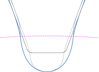
To identify stress concentration, an FEM calculation is used to analyze the tooth root stress present for root rounding or grinding notches. 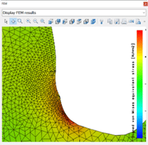 A 2D FEM calculation is sufficient to determine the tooth root stress caused by grinding notches.
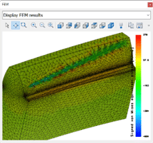
A 3D FEM calculation is recommended if the influence of a flank modification is to be taken into account.
Natural twist- Simulation of twist created by threaded wheel grinding
- Use of LTCA to analyze noise excitation
|
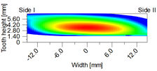
Natural twist occurs during threaded wheel grinding of helical cylindrical gears with crowning. This twist is simulated in KISSsoft and rated with the loaded tooth contact analysis (LTCA). 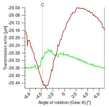
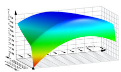
The loaded tooth contact analysis shows the behavior under load, such as stress distribution and contact pattern. The transmission error (PPTE) is used to analyze the noise excitation of gears. 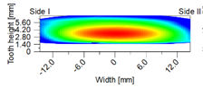
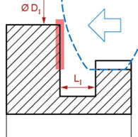
Collision check when Power Skiving & honing- Check tool overtravel
- Tool shaft collision with the gear shoulder
|
KISSsoft analyzes the possibility of the tool colliding with the workpiece, on the basis of the cross-axis angle and tool diameter, shaft contour or internal shaft diameter. 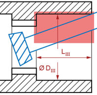 For a detailed analysis, the verification for a potential collision by Gleason is recommended.
Non-involute gear teeth- Import non-involute gear profiles
- Create tool profile for generating cutting processes
|
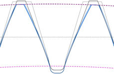
The tooth forms for non-involute gears can be imported in 2D DXF format or created directly in KISSsoft. Tooth forms include straight flank, cycloid or sprocket profile. KISSsoft verifies the feasibility using generating cutting processes and calculates the tool reference profile or specific tool form.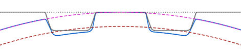
The tool's reference profile or specific tool form can be exported in 2D DXF format and used for the tool’s manufacture.
Measurement grid data- Generate measurement grid data
- Export data in GDE or GAMA™ format
|
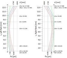
To control a Coordinate Measuring Machine, the measurement grid data and the normal vectors for the tooth flank are exported from KISSsoft. This data is available for cylindrical and beveloid gears.
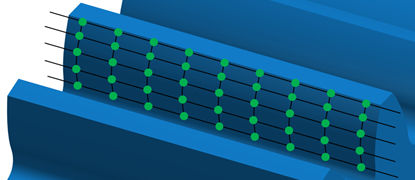
GAMA formats can be used for quick and secure data transfer between KISSsoft and a Gleason metrology system. GAMA enables the transfer of macro geometry data of cylindrical gears directly to the metrology system.
The export format for GDE is defined in the VDI/VDE 2610 guideline. This guideline provides an exact and unique method for describing gear geometry and manufacturing data.
Calculating the tooth thickness allowance- Calculate the base tangent length and measurement over pins
- Available for splines and deep tooth forms
|
The base tangent length or measurement over pins is required to measure the tooth thickness.
Using the tooth form analysis, these values can be calculated for every position on the tooth and machining step, even for non-involute gears.
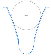 Pre-machining
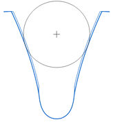 Finishing
A flattened measuring ball can be defined for spline profiles, to prevent the tooth root from being touched.
In the case of deep tooth forms, the ball or roller diameter is automatically calculated to take a correct measurement outside the tip circle.
"Design-Manufacture-Measure"- Evaluate manufacturing influences on noise
- Simulate contact pattern under load
|
The "Design-Manufacture-Measure" loop integrates KISSsoft, Gleason gear manufacturing machines and metrology systems in a holistic process.
To evaluate manufacturing deviations and their effects on the gear meshing characteristics, the measured flank topography is imported into KISSsoft, analyzing its load behavior and noise excitation using the contact analysis. 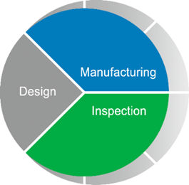
This process allows to verify manufactured gears and to ensure the required quality of the transmissions.
Master gears- Use existing master gears
- Testing of complete active flank
|
For roll testing of a production gear and its active flanks meshing with the counter gear, the master gear is calculated. It is important that the master gear covers the full active flank of the production gear, but no interference e.g. in the tooth root area does occur.

Preferably, the use of existing master gears is targeted. The master gears can be entered in KISSsoft and the rolling with the production gear can be analyzed. The roll testing can be done on a Gleason roll testing machine.
A trial version is available upon request at KISSsoft. |


 Creating a gear chamfer during premanufacturing requires a separate tool. The angle and size of tooth tip chamfer can be defined in KISSsoft based on the required tip form circle, considering different tolerance conditions.
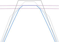
 This results in improved tool life and optimized root form circle to achieve the highest contact ratio.
 In KISSsoft, the tool module and pressure angle are converted to achieve the same base circle pitch. The generated root form circles and root roundings can be graphically displayed and checked for potential meshing interference.