When someone in the molding industry speaks of regrind quality, they are usually referring to the consistency of the granules that are produced after parts or runners are reground. A consistent granule size with a minimum amount of fines (small dust or flake-like particles) or excessively long granules is desired for a few reasons. A consistent granule size will help to ensure uniform melting in the molding process the next time the regrind gets used. Non-uniform melting results in the molten plastic having inconsistent viscosity, which in turn can result in inconsistent dimensions in your molded part. Fines in the regrind can lead to black specking in a light-colored material due to the fact that the small particles melt sooner and may degrade during processing. Since dimensions and black specking can be detected through physical and visual inspection, there is no need to discuss them any further in this paper.
Of even greater importance than granule size is the regrind cleanliness (lack of contaminants) and the controlled exposure to heat and shear. It is during the process of creating and using regrind that contamination has the best chance of being introduced into the molding process. For this reason, everything stated in the earlier section on material handling applies in particular to the regrind. Also many molders do not keep sufficient tabs on the number of heat histories that the regrind has seen and will not discard material after an acceptable number has been reached. This can result in material properties that are greatly reduced due to the excessive amounts of shear and heat seen by the plastic. A gear could be produced that meets print specifications (dimensions and material call out) and has the same appearance, but it could fail due to reduced physical properties.
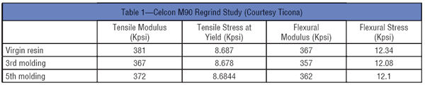
If regrind is properly handled, plastic parts made from unfilled plastics can typically be molded and remolded at least five times with virtually no drop in material properties. (See Table 1 showing the regrind properties of Celcon M90 acetal material, which is one of the most common plastic gear materials in use today.) This information should not be construed to say that plastic can be reground and reused indefinitely. With each remolding, a higher percentage of polymer chains will have been reduced in length or degraded. Polymer chain length or molecular weight is directly related to key material properties such as tensile strength, flexural strength, fatigue strength and creep resistance. When the percentage reaches a critical limit, more significant drops in properties can be expected. For materials with fillers, it is more important to keep the percentage of regrind or the number of times the material gets reground (referred to as number of heat histories, generations of regrind or regrind pass) to an amount suitable for the requirements of the application. This is mostly due to the fact that the average fiber length will get reduced each time the material gets reground in the grinder, sheared in the molding machine barrel and sheared passing through the gates of the mold cavity.
It is difficult to find published data on regrind percentage properties; even if it was readily available, it would be difficult for a designer to use confidently because so much of the properties are dependent on how the molder chooses to handle the regrind. As a result, gear designers often specify no or low regrind percentages allowed in their plastic gears. A better option is to find a molder committed to the highest quality regrind and to do some up-front testing with gears containing varying percentages to prove that the material will have the properties required for your application. A molder with dedicated press side granulators versus large-scale bulk grinders will be more successful at keeping regrind clean and manageable. Knowing the gear molder has specific procedures in place for tracking the number of heat histories seen by the regrind and discarding the material after a maximum has been reached are most important.
Moisture. Many plastics including nylon are hygroscopic, because parts of the polymer chain are attracted to water molecules, often through hydrogen bonding. This attraction to water may cause a plastic to swell a little bit, but by itself is not necessarily a bad thing. In fact, in the case of nylon, this little bit of water that gets into the plastic actually helps some properties, such as impact strength and toughness. The problem really occurs when certain plastics and water are brought together under high heat and high temperature, like in the injection molding process. Nylons, polyesters, polycarbonates and polyurethanes are examples of plastics that can undergo degradation as a result of moisture in the pellets. Because of this, many plastics will have drying requirements to drive off this water prior to processing. If proper drying does not take place, hydrolytic degradation can take place, causing polymer chains to break down, resulting in a significant reduction in the physical properties of the plastic. There may be some visible signs in a molded gear indicating moisture was present in the plastic pellets, but not always and not with all materials. The end result could be a hidden defect that does not get detected until a gear gets into the field.
On the other end of the spectrum would be over-drying of the plastic resin through either excessive time or temperature. For most materials, the material manufacturer will recommend that most but not all of the moisture be removed prior to processing. For nylon, that ideal range is generally understood to be 0.08%–0.2% moisture content. It can be argued as to whether removing too much moisture by itself has a harmful effect on the end product, as the end product itself will pick up any required moisture after molding in order for the product to avoid becoming possibly too brittle. Removal of too much moisture generally shows its negative effects during processing, as the material generally becomes more stiff and viscous. The bigger problem is that prolonged exposure time at elevated temperatures usually results in oxidation and subsequent degradation of the plastic.
To avoid a gear with poor physical properties getting into the field, it is critical first and foremost that the gear molder has proper drying equipment. The equipment must accurately control temperature, airflow and dew point of the drying air. The equipment must utilize a desiccant bed for removing the moisture that gets driven out of the plastic with time and temperature. The equipment must be properly sized to avoid under drying or thermally degrading the plastic. Throughput of the molding pellets in the molding machine (or machines in the case of a central drying system) should be calculated and time- and temperature-adjusted to the material manufacturer’s recommended specifications. Additionally, moisture analyzing equipment can be used to regularly sample the moisture levels of the molding pellets.
Thermal degradation. Thermal degradation can also take place in the molding machine barrel. This degradation is also time- and temperature-dependent. To avoid excessive time in the barrel, the molding machine needs to be properly sized compared to the size of the molded shot. The easiest way to assure that exposure time is not excessive is to follow the second half of the 80/20 rule where the shot (part and runner) size is not to be less than 20% of the shot capacity of the molding machine barrel. So even at the longest of cycle times, residence time will be less than five minutes. Most materials, if the material supplier’s recommended processing temperatures are not exceeded, will not degrade in that amount of time. When hot runner molds are used, the extra residence time in the manifold must also be considered. Thermal degradation due to residence time can also occur if the molding machine is left idle at processing temperatures for extended amounts of time before parts are molded and collected. If the gear molder uses barrel temperatures beyond what is recommended by the material supplier, the amount of time the plastic can stay at that temperature without degrading is greatly reduced. If thermal degradation occurs, the result will be a molded gear that is excessively brittle (poor impact strength) and has lower strength than expected. In particular, gears that run at high speeds or stop and start quickly under load are susceptible to impact failure.
Armed with this information, the end user of the gear should be sure to know the molding machine size that the gear molder will be using. Be careful to avoid a situation where your gears can get qualified (initial product testing and tool approval) in a properly sized molding machine and then switched into an oversized machine when the tool is run during normal production. Always ask your gear molder for the machine and processing information used to produce your parts.
Molded-in stress. All injection molded parts have some level of molded-in stress. Molded-in stress occurs as a result of the polymer chains being frozen in anything but their preferred perfectly random state. The injection molding process will always impart some degree of stress or orientation into the plastic during the fill and pack phase. Once the plastic material makes contact with the much cooler surface of the mold, some portion of the polymer chains will quickly begin to cool and get frozen in a non-random (highly orientated) state. The polymer trying to get back to its preferred state is the source of the stress. Differential cooling rates across the thickness of the part will create a similar condition that results in molded-in stress. Crystalline materials with their high shrink rates are the most susceptible to high levels of molded-in stress. Excessive molded-in stress is most commonly a result of excessive shear, excessive pressures or cold molds used in processing the part.
This excessive molded-in stress, combined with the normal stress put on a gear tooth during operation, could contribute to premature failure of the molded gear. Excessive molded-in stress will also leave the gear susceptible to twisting and/or warping if the temperature of the gear in service is high enough to allow the polymer chains to begin to move. In other words, the gear could be flat at the time of first inspection but end up warped later on when in use. Localized stress areas in the gear are sites where environmental stress cracking (ESC) can occur. ESC is the premature initiation of cracking and embrittlement of a plastic due to the simultaneous action of stress and strain and contact with specific fluids.
Excessive molded-in stress is not visible to the naked eye. This phenomenon can be shown with the use of cross-polarized light with one filter placed on either side of the molded sample and light passed through all three pieces. The areas where the polymer chains have remained in a more random state will appear black while the areas of high-stress and orientation will exhibit a multi-colored pattern due to birefringence as the polarized light passes through the molded sample.
See Figure 3 showing two 24 DP, 36-tooth gears molded using polycarbonate in the same mold with different processing conditions. Polycarbonate was used because the transparency allowed for evaluation using polarized light. Any effects seen in the low-shrink polycarbonate gear can be expected to be further exaggerated in a high-shrink semi-crystalline gear. The first gear was molded using a high 200°F mold with a moderate pack pressure of 8,000 psi. The second gear was molded using a low 100°F mold and a relatively high pack pressure of 14,500 psi. In the first gear, the area of high stress is mostly localized along the centerline of the tooth. This is indicative of the normal stresses generated as a result of differential shrinkage between the plastic closest to the mold surface and the more insulated plastic at the center of the part. It can be seen in the second gear that the area of high stress extends farther out towards the edge of the gear teeth and is also present in the root area between teeth. This additional stress, particularly at the root, could lead to problems when stress and heat is generated during gear meshing under load.
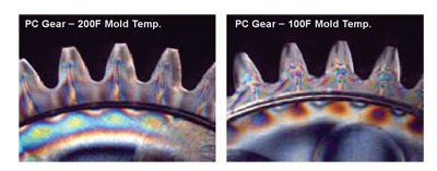
Figure 3—Molded-in stress in polycarbonate gears.
Process conditions, such as low mold temperature and excessive pressures that contribute to molded-in stress, may be used by the gear molder to try to compensate for a mold cavity that is too small due to incorrect prediction of shrinkage by the molder or mold maker. Additionally, low mold temperature might be used in an effort to reduce cycle time (increase production yield). Be sure to use a gear molder who has a deep history and understanding of exactly how gear materials will shrink. Also be sure that the gear molder understands the importance of proper process conditions and will build or adjust a mold based upon a good molding process rather than cheating on the process conditions to compensate for an incorrectly sized mold.
Voids. Voids are similar to molded-in stress in that they are a result of differential cooling rates across the thickness of a molded part. The outer skin of the molded part that is in contact with the mold cavity wall will cool quickly, while the inner section cools at a slower rate. This quick cooling at the wall freezes the material in position near the cavity wall, while the inner material continues to shrink and experience much higher contraction. This can create a vacuum between the inner and outer layers of the part. If additional plastic material cannot be fed into this center section of the part during the packing phase of molding, a void will result. In many cases a void in a plastic part, particularly if it is small, will be harmless and will have no effect on the end properties of the product. If the void is large enough or ends up in a high-stress area of the part, a failure could occur.
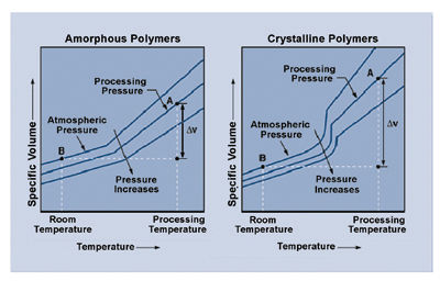
As shown earlier in Figure 2, crystalline materials experience a large volumetric change as the part cools below the melt temperature. This means that crystalline materials often used in gear applications are much more likely to have voids. In anticipation of this, the molder must be sure to have sufficient pack times and pressures in the molding process. Mold temperatures should be kept high enough to promote a more even cooling rate across the part width and to allow material to flow to the center sections of the part for as long as possible.
Weak weld lines. A weld line on an injection molded plastic part is formed where two flow fronts meet and join. Weld lines are formed when a part has multiple gates, but can also be seen where a single flow front is forced to split as it molds around an internal feature in the mold cavity, like the core pin that forms the ID. The type of weld line resulting from the flow front splitting is sometimes referred to as a meld line. Weld lines are all but guaranteed in plastic molded gears, regardless if one gate or multiple gates gets used. The tensile strength of the plastic material across a weld line is always going to be weaker than the same material without a weld line. Slight cooling and orientation at the flow front prevent the polymer chains in one flow front from becoming completely interweaved with polymer chains from the opposing flow front. The weakening effect of weld lines is greatest when molding plastics have fiber fillers. The first reason is that there are fewer polymer chains available to become interweaved at the flow front (a 30% fiber-filled plastic has that many fewer polymer chains at the flow front). The second reason is that orientation of the fibers at the flow fronts results in fibers mostly running parallel to one another. These parallel fibers, which offer little strength benefit, are less likely to cross over to the adjoining flow front and provide reinforcement at the weld line. Processing aids or other additives incorporated into a plastic can further weaken weld lines as these tend to migrate out to the surface of the flow fronts, acting as a barrier between the polymer chains.
In some applications, a part design or gate locations in the mold can be modified to make sure weld line ends up in a low stress location of the part where this weakening effect is not a factor. For a molded plastic gear, where there are gear teeth around the full 360 degrees of the part and where there is an ID in the center of the part, it is not really possible to move the weld line to a location where it doesn’t matter. This is especially true since plastic gears are generally fine pitched, and keeping the weld line in the center of a tooth as opposed to the root would not be possible. Many plastic gears are press fit onto shafts and therefore require good hoop strength around the ID. The splitting of the plastic hub is a common failure mode where weak weld lines exist. This splitting of the plastic hub will very often take place long after the gear has been press fit onto its shaft. The reason is that in order for a plastic material to have good resistance to creep, there must be good interweaving of polymer chains.
This leaves the only defense in the hands of the molder to do what is necessary to produce a weld line that is as strong as possible. Producing a strong weld line requires time, temperature and pressure. The polymer chains need sufficient time to interweave before cooling to the point where the chains become immobile. This time is created by keeping the temperature of the melt and mold higher for longer. Pressure in the melt can also help in forcing the two flow fronts together. A gear molder who chooses to run temperatures of the melt and mold as low as possible to speed up the cycle or increase part dimensions will seriously compromise the strength of the molded gear.
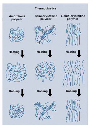
Low crystallinity. The two most common plastic gear materials in use today are acetal and nylon. Both of these are semi-crystalline materials that require crystallinity to achieve their best physical properties. Acetal is a highly crystalline material with a very flexible molecular backbone that allows for quick crystallization. Acetal crystalline content can typically range from 75% to 85%. Nylons (like a nylon 6/6) can have crystalline contents that range between as low as 10% up to roughly 60% depending on molding conditions and part geometry.
Up to this point, it’s been discussed how a molder can damage the plastic or create a physical defect in the molded part. With crystallinity, the molder is given the power to effectively custom-make the plastic into something it is or is not intended to be. It was discussed in the earlier section on crystallinity that above the melt temperature of the polymer, the polymer is essentially 100% amorphous. It is upon cooling that the crystalline structures are formed. How long the plastic dwells at higher temperatures before freezing will determine how crystalline the plastic becomes. This dwell time for any given part is dictated by cooling rate, which is most heavily influenced by mold temperature.
Material suppliers give a recommended mold temperature range to the molder armed with the knowledge of the temperature at which optimum crystallinity (size and quantity) occurs. In the case of nylon, the acceptable range may be fairly wide given that you can make a good part at the lower end of the temperature range; it will be a generally softer and tougher material given the higher amorphous content in the material. In general for gearing applications, tensile strength, flexural strength and hardness are most important, so a mold temperature on the higher end of the range should be used.
Figure 4 shows microtomed section views of a nylon 6/6 gear molded with both low mold (100°F) and melt (540°F) temperatures. This combination results in a gear with a lower and much less homogeneous crystalline content than what is possible in nylon 6/6. Note in the first photo of Figure 4 where very clearly defined flow lines (both light and dark) can be seen throughout the gear. Large spherulites are formed along the light colored lines. This is shown very clearly under higher magnification in the third photo of Figure 4, where very large spherulites (as large as 0.003 in.) can be seen among a sea of smaller but still varying sized spherulites. The darker lines seen are areas of low or no crystallinity. This inconsistent morphology results in a material with varying properties throughout and also results in weak boundaries between the larger and smaller spherulites. Many properties such as chemical resistance, crack resistance, hardness and wear resistance can be compromised in a gear molded under these conditions. Also of note in this gear is the relatively thick amorphous skin, which measures approximately 0.004 in. Because hardness and wear resistance are properties dependent on crystallinity, this particular gear could wear deeper and faster than a nylon 6/6 gear molded with higher mold and melt temperatures.
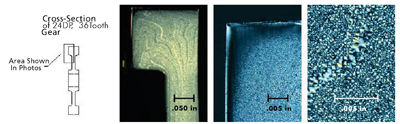
Figure 4—Nylon gear crystalline structure 100°F mold, 540°F melt.
Figure 5 shows microtomed section views of a nylon 6/6 gear molded with both high mold (200°F) and melt (570°F) temperatures. This gear shows a higher and much more consistent crystalline content than the one molded with lower mold and melt temperatures. The spherulites are tightly packed and are a consistent size of about 0.0003–0.0006 in. This will result in higher and more consistent material properties. The amorphous skin is comparatively thin at about 0.0006 in., which should result in less wear.
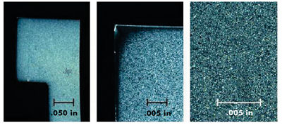
Figure 5—Nylon gear crystalline structure 200°F mold, 570°F melt.
Post-mold shrinkage. So far in this paper, a number of problems that result from molders using excessively low mold temperatures have been discussed. These included voids, molded-in stress and low crystallinity. There is one more very important problem that can have significant consequences in terms of how a molded gear will function in service.
Post-mold shrinkage is when a molded part continues to shrink well after the part has been molded and cooled down to room temperature. For most all molded plastic parts, there is some amount of stress relief and shrinkage that occurs over the first 24 hours or so after molding. This is generally understood and is not a problem to deal with. It is the shrinkage that can occur weeks and months later that spurs the conversation of post-mold shrinkage.
As stated earlier, if polymer chains are frozen in a non-random state, internal stresses result inside of the material. Polymer chains will continue to try to move to the preferred random state. And even though a plastic may be a solid at room temperature, polymer chains still have some amount of mobility as long as the temperature is above the Tg of the material. Acetal has a Tg of 9°F, which means that even at room temperature, the polymer chains have some mobility. This mobility, albeit minimal, allows the material to continue to shrink and stress relieve long after molding. Nylon has a Tg somewhere between 70–140°F (depending on how much moisture it has absorbed), which means nylon will experience overall less post-mold shrinkage, and it will usually require higher than room temperatures to start to happen. For both acetal and nylon, post-mold shrinkage increases quickly as the service temperature increases.
Figure 6 shows post-mold shrinkage versus exposure temperature for acetal molded at various mold temperatures. It is easily seen that post-mold shrinkage is much higher for parts molded with a colder mold. A cold mold restricts initial plastic shrinkage as the molded part gets frozen into a larger, more highly stressed form (the shrinkage that needs to happen does not happen initially). On the contrary, a hotter mold allows shrinkage to occur more naturally, resulting in a smaller, less stressed molded part (the shrinkage happens now instead of later when an end user may not expect it). Because of post-mold shrinkage, a gear could be molded that meets all physical measurements of size and form at the time of first inspection. If measured again many weeks later, especially if the gear was exposed to higher temperatures, it could measure well out of tolerance.
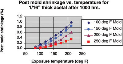
Figure 6—Post-mold shrinkage of acetal (Taken from DuPont Molding Guide).
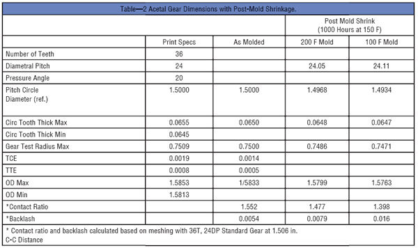
Table 2 demonstrates what the effect might be on a typical plastic gear’s dimensions when exposed to 150°F for 1,000 hours. A gear that measures nominal for all dimensions at the time of molding can end up being out of spec. by 0.0005 in. on the gear test radius (GTR) and 0.0014 in. on the OD when a 200°F mold gets used and end up being out of spec by 0.002 in. on GTR, and 0.005 in. for OD when a colder 100°F degree mold gets used. This will translate into reduced contact ratios and increased backlash. It is also very possible to have a gear that was flat and round at the time of initial inspection become warped or out of round as a result of excessive post-mold shrinkage.
The best way to minimize these effects of post-mold shrinkage is to minimize stresses during molding (minimize shear and avoid excessive pack pressures) and to use a sufficiently high mold temperature.
Conclusion
It is understandable how a molder would knowingly or unknowingly move to using process conditions that produce a part more prone to failure than a part molded at optimum process conditions. The traditional gauge of quality, physical measured dimensions, tells the molder that if the part measures well, it is a good part. A good gear molder should know that there is more to quality than what meets the eye.
The goal of this paper was to provide knowledge to both end users and molders of plastic gears on the crucial role that the molder has in determining the final quality of a plastic molded gear. The end user should use this knowledge to make the best decision when choosing a gear molder. The decision process should explore the molder’s systems, procedures, equipment and experience in molding high-quality plastic gears. This same knowledge then needs to be used by the gear molder to ensure that decisions regarding the molding process and material handling are made with the end properties of the molded gear as priority number one. Priority number two should be molding parts that meet print specifications for dimensions. If priority number one and priority number two cannot be achieved simultaneously while molding at a profitable cycle time, then some important decisions need to be made. The decisions, if made properly, should result in having an injection mold that was built around a good process and not the other way around.
Acknowledgements: Bill Stec, Columbia Station, OH – microtome and cross polarized photography.
Timothy Vale is director of research and development at ABA-PGT, Inc. where his focus is on pushing the envelope of what plastic gears are capable of through the use of novel injection mold designs and advanced plastics processing techniques. He earned both his bachelor of science and master of science degrees in plastics engineering from the University of Massachusetts at Lowell. Previous positions held at ABA-PGT include engineering manager, project manager and process engineer. In these positions, Vale has successfully taken hundreds of varying plastic gear concepts of all types and materials from prototype and design to high-volume, high-precision production.
Printed with permission of the copyright holder, the American Gear Manufacturers Association, 500 Montgomery Street, Suite 350, Alexandria, Virginia 22314-1560. Statements presented in this paper are those of the authors and may not represent the position or opinion of the American Gear Manufacturers Association.