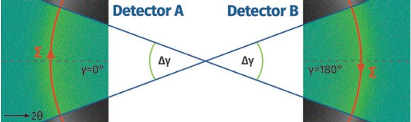
Figure 5—The use of 2D detectors allows for the collection of significantly more diffraction data.
In addition to improving the sensitivity and speed of the system, the 2D detector method employed by the Xstress DR45 combines the benefits of 2D detection systems, such as mitigation of difficult diffracting conditions like textured or large grains, with the high quality and trusted results of the sin2ψ method. Beyond that, the multiple orders of magnitude improvement in speed allows for some truly game-changing capabilities: continuous movement measurements (or Sweep mode).
Diffraction systems utilizing the tried-and-true sin2ψ method have always followed a standard sequence of operation (or Standard mode, shown in Figure 6): 1, move X-ray incident beam and detectors to position; 2, Expose the sample the incident X-rays and collect diffraction data with detector; 3, Repeat 1–2 as necessary to satisfy the measurement specification such asEN15305. This type of measurement sequence is standard on nearly all diffractometers except for systems utilizing methods not in accordance with internationally recognized standards.
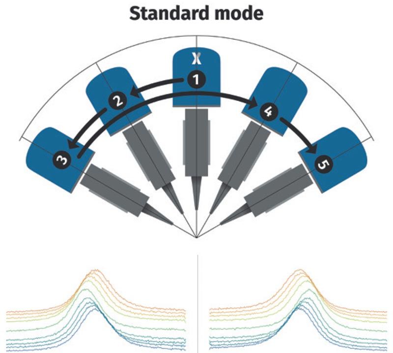
Figure 6—Standard mode x-ray diffraction systems use a time consuming sequence of individual scans.
The speed of the detection system on the Xstress DR45 allows the diffractometer to collect “snapshots,” much like video frames, while it is moving (Fig. 7).
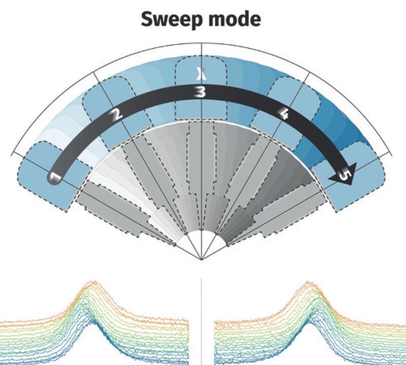
Figure 7—The Xstress DR45 is able to scan continuously, greatly improving inspection speed.
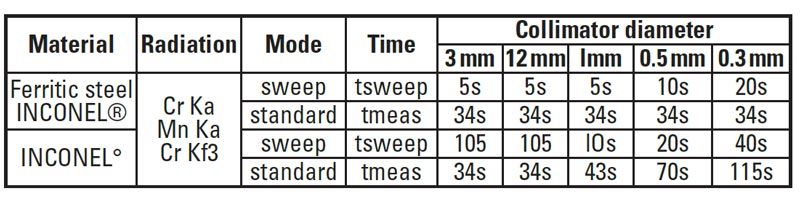
The result is a large improvement in total measurement speed over the already fast Standard mode speed provided by the Xstress DR45. Measurements on spots 1 mm in diameter or larger are performed in 5 seconds. Measurements on spots less than 0.5 mm in diameter can be performed in as little as 20 seconds. These speeds open the possibility of shot peen verification on gear teeth or roots which is fast enough to keep up with production in high-volume environments.
Grinding Burn Detection
Grinding is a crucial step in gear manufacturing, and it frequently presents manufacturers with a critical question: How fast can I grind without generating a grinding burn? Faster cycle times are always desirable but greater infeed, wheel speed, etc. can result in more energy, or heat, being deposited into the workpiece (Fig. 8).
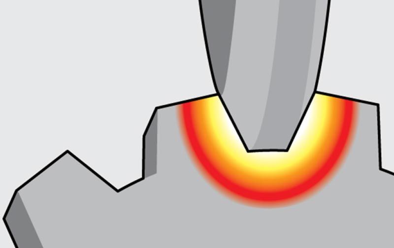 Figure 8—Aggressive feeds and speeds can result in grinding burn.
Grinding burn occurs when the heat generated in the workpiece during grinding is great enough to act as a tempering process or, in the case of even higher temperature, a re-heat treatment of the affected surface. The result of this localized thermal event is a transformation of the microstructure, much the same as what occurs during heat treatment. The affected volume of material is transformed from a desirable microstructure, such as tempered martensite, to an undesirable mix of over-tempered martensite (or softer ferrite, etc.) and untempered martensite. The transformed microstructures have differing densities but, squeezed into the same space previously occupied by the desirable microstructure, then must be compressed and/or pulled apart in order to fit. This compressing or pulling manifests as residual stresses in the material.
The traditional method for detection of grinding burn is the Nital etch process. Nital etching involves exposing the surface of the material to different chemicals, including Nital (nitric acid and alcohol) and hydrochloric acid. The process takes advantage of differential dissolution, where the Nital mixture attacks phases such as ferrite, cementite, etc. differently. The result is that some visual contrast exists between the desirable tempered martensite microstructure and the undesirable over-tempered or untampered generated by grinding burn.
Though it is a traditional method with decades of use the Nital etching process has some downsides: it is subjective, requiring the practitioner to interpret litera l shades of gray; it requires the use of possibly dangerous chemicals, often with nontrivial handling and disposal requirements; in most cases it is destructive, as etched surfaces may not be suitable for use in service. Another limitation inherent to the Nital etch process is that it is insensitive to stresses—its mechanism of action is to reveal transformed microstructure. In the case where grinding burn occurs during a roughing pass, only to be partially cleaned up by a finish pass, the Nital etch process can be ineffective at revealing the partially cleaned up transformation products. Despite partial cleanup of the transformed layer, subsurface tensile stresses typically remain. This “hidden” burn leaves the component susceptible to early failure. Stresses induced via grinding burn typically peak at 20–50 micrometers below the surface. In the case of partial cleanup of grinding burn during the grinding process a subsurface tensile peak typically remains (Fig. 9).
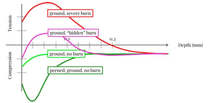 Figure 9—Nital etch can sometimes miss some forms of grinding burn.
An alternative method to detect grinding burn is Magnetic Barkhausen Noise (MBN). It is a repeatable, objective measure that is nondestructive (Fig. 10). Furthermore, MBN is sensitive to both stresses and microstructure in the measured volume which makes it ideally suited for detection of grinding burn in cases of partial cleanup.
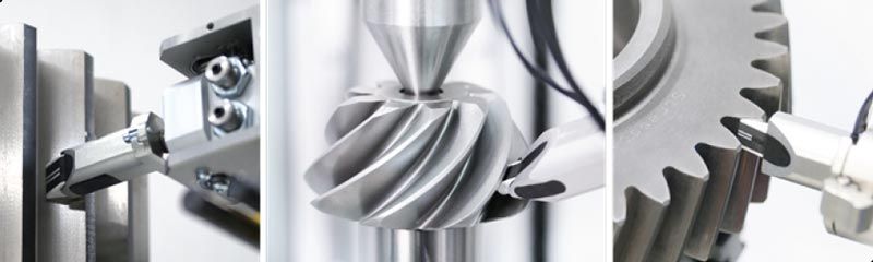 Figure 10—Magnetic Barkhausen noise analysis is an alternative to detect grinding burn.
Stresstech’s Rollscan Barkhausen Noise analyzers take the MBN signal and reduce it to a single number measured in real-time. This allows the user to traverse an MBN sensor across a surface, manually or via automation, and get a live measurement or even a surface map.
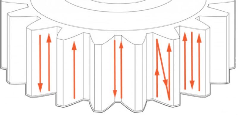
Automated systems are programmed in the same manner as an analytical gear checker with the ability to map the surface of the flank to the level of spatial resolution required for the applicationby utilizing Stresstech’s EasyGear software (Fig. 11). Gear flanks and roots, along with various other surfaces such as faces, ODs, and IDs are all measurable with MBN instruments (Fig. 12).
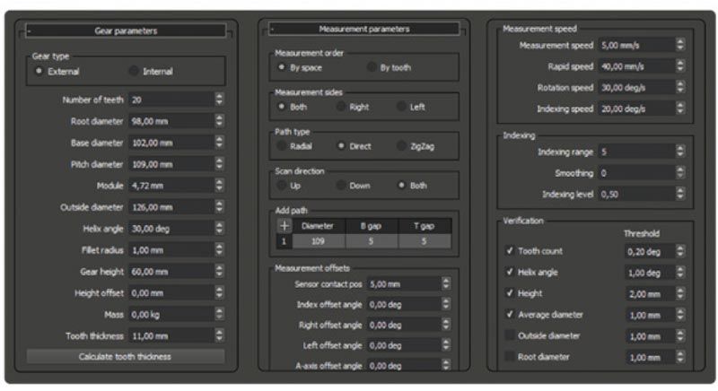 Figure 11—Stresstech EasyGear software for programming of automated gear testing.
 Figure—12 MBN instruments can measure gear flanks, roots, faces, ODs and IDs.
Customized sensors are sometimes required depending on the geometry of the surface to be inspected. For example, gear flanks and gear roots are typically measured with dedicated sensors which facilitate the sensor contacting the area of interest (Fig. 13).
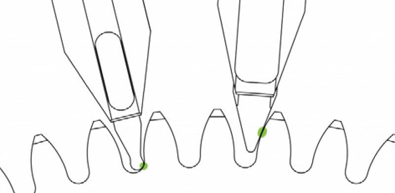 Figure 13—Customized sensors can be used, depending on the surface to be measured.
In the case of more complex geometries, such as hypoid gears, custom sensors are utilized, and sensor movement paths are generated along complex curves generated point-by-point (Fig. 14).
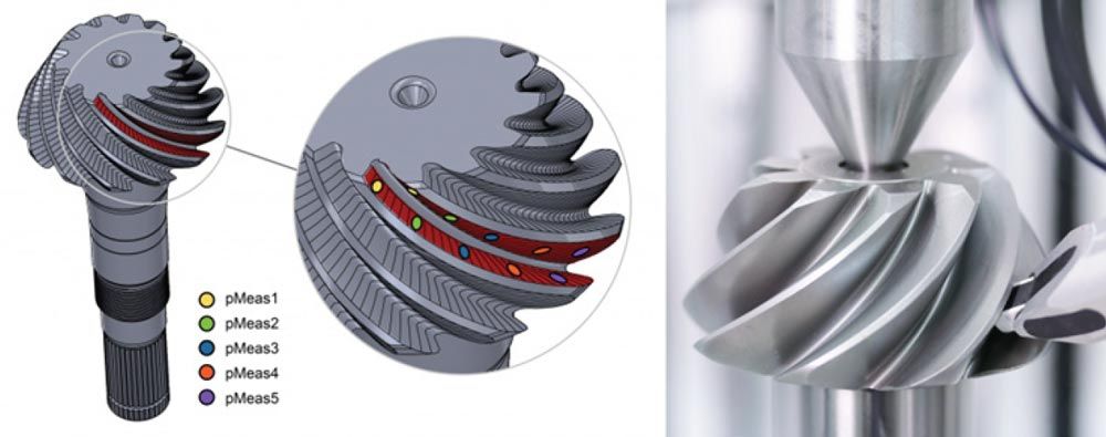
Figure 14—Complex geometries can be accommodated via special sensors and point-by-point control of the sensor path.
The result of a measurement sequence is a series of scans, or plots, similar to the output of an analytical gear checker. Lower and more consistent measurement values, essentially flat scans, are typically found in acceptable parts free of grinding burn (see the green line in Figure 15). In the presence of a grinding burn the MBN signal increases (see the red line in Figure 15).
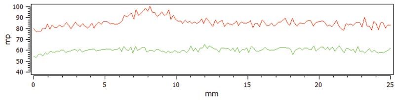
Figure 15—In this chart, the red line represents MBN signal increases, indicating the presence of grinding burn.
Multiple scans or passes per flank, performed at varying diameters, can be combined into a surface map. This provides the type of visual indication that Nital-etch users are accustomed to seeing, with the added benefit of objective, repeatable values (Fig. 16).
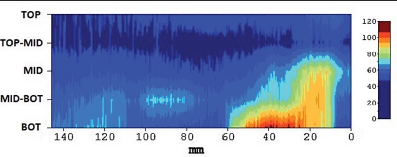
Figure 16 Multiple scans or passes per flank can be combined into a surface map.
By comparing the relative MBN values to a quantitative method such as XRD the MBN values can be contextualized, and proper rejection/acceptance criteria can be developed. The most common method of developing rejection criteria involves comparing the MBN value to the maximum subsurface stress, measured via XRD, similar to the recommended practice in SAE ARP4462b. Such a comparison allows the user to choose an MBN value limit that corresponds to subsurface tensile stresses, or some other limit depending on the application and the design requirements for the component under test (Fig. 17).
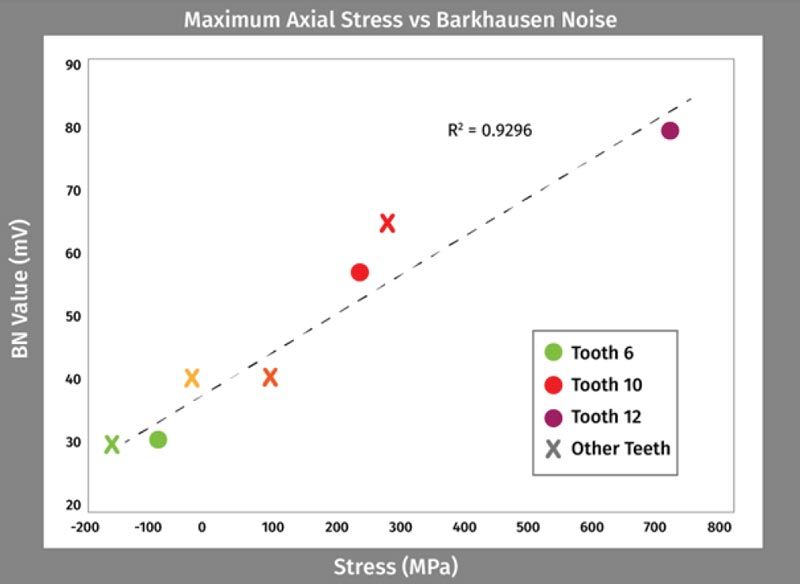
Figure 17 Data from MBN scans can be shown against simple rejection/acceptance criteria for easy evaluation.
Conclusion
Gears present challenges to many traditional testing methods both destructive and nondestructive. In cases where residual stress is critical, as is the case in shot-peened gears, verification of the shot-peening process via XRD can be fast enough to keep up with your production. This is especially true when utilizing state-of-the-art instruments such as the Xstress DR45.
Nearly all gears in precision applications have ground flanks. Sometimes they also have ground roots. Detecting grinding burn on these surfaces with maximum sensitivity and repeatability, all while avoiding costly scrap, is achievable using Magnetic Barkhausen Noise. Additionally, the method can be fully automated to provide measurable feedback for process control.
stresstech.com


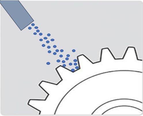 Figure 1—Shot peening involves blasting the surface of a component with hard "shot."
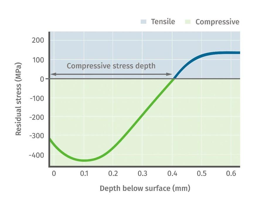
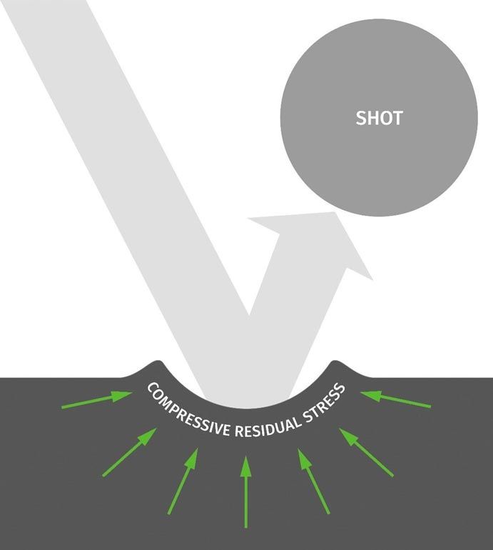 Figure 2—Shot peening results in a thin layer of compressive residual stress.