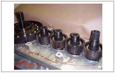
Figure 6—Baseline gear train installed in half of the test gearbox.
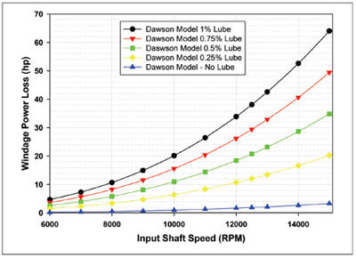
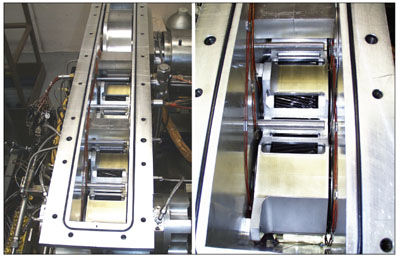
Figure 7—Test gearbox cover removed showing gear shrouding.
The gears shown in Figure 6 were the as-ground components. The gears were subsequently superfinished and reinstalled in the test gearbox. These gears are shown for the entire gear train in Figure 8 and a close-up in Figure 9.
Figure 8—Entire gear train after superfinishing.
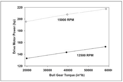
Figure 9—Close-up of a superfinished gear.
The as-ground gears that were run extensively before superfinishing had an average surface roughness of 3.91 µin. Ra and 28.3 µin. Rz. The gear surfaces after superfinishing had a surface roughness of 1.71 µin. Ra and 13.2 µin. Rz, where Ra is the average surface roughness and Rz is the maximum surface roughness. These measurements represent an average of three measurements taken radially across one tooth on each gear.
Data Acquisition. The test facility data system monitors three important facility parameters during operation. Speed, torque (supplied torque and loop torque) and temperature measurements were made during all the testing conducted. The test system loop torque is measured on the shaft connecting the bull gears from the test and slave gearboxes. A telemetry system was utilized in this location.
The data recording system used in this study is capable of taking data from all parameters at a rate of one sample per second. Tests in this study recorded data every two seconds. The data is displayed to the test operator in real time. Data is stored in a spreadsheet format, and each sensor can be viewed at any time during a test and when post processing the results.
Test Operation. The test procedure for collecting the data to be presented was the following: For a given set of conditions (speed, torque, lubricant pressure and lubricant oil inlet temperature), the facility was operated for at least five minutes, or until the temperatures of interest had stabilized (or reached steady state).
Experimental Results. Tests were conducted and operational conditions maintained at steady-state conditions. As mentioned, the primary data from the testing include temperatures, speed and torque. The following data will be presented as the subject of this paper: temperature measurement location versus typical operational conditions; lubricant jet pressure (or flow); lubricant inlet temperature effects; and a comparison of the baseline to superfinished gears.
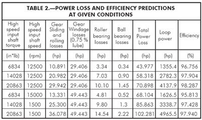
The first set of results is presented as an example of the large amount of data taken throughout this study. The test shown in Figure 10 was attained for the superfinished gears, keeping the lubricant inlet temperature and pressure constant. In Figure 10, the array (thermocouple #5) and rake (thermocouple #3) mid-temperature locations are shown for seven conditions of this particular test. The seven conditions included a warm-up; then three conditions of torque at 12,500 rpm; and finally the speed was increased to 15,000 rpm and the three torque conditions repeated. The test operational conditions can be found in Table 2 with a summary of some of the other data of interest. In this figure, typical for this gear system, the array temperatures were always much higher than the corresponding rake temperatures at the same location. As shown in this figure, the maximum temperature over the inlet lubricant temperature was on the order of 180°F.
Figure 10—Superfinished temperature data at mid-face rake and at array center for all sensor locations (conditions shown in Table 2, one scan = 2 s, 160°F oil inlet temperature).
Next, in Figure 11, a single meshing location is shown for all rake positions and for the vertical thermocouples from the array (thermocouples 1, 5 and 9) for the 2nd–3rd idler location. Once again the same data set as in Figure 10 and Table 2 was used. In Figure 11, the highest array temperatures exceeded any temperature on the rake. Also, the rake temperatures are not uniform across the face width. From the data shown, the difference in rake temperatures was as high as ~50°F.
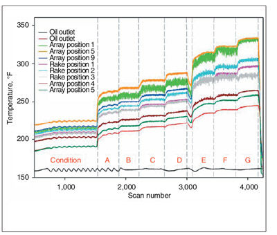
Figure 11—Superfinished gear test data comparing 2nd–3rd idler location for rake and array data (condition shown in Table 2, 160°F oil inlet temperature).
Another test that was performed was to vary the lubricant jet pressure from the nominal 80 psig to two lower settings. This data is shown in Figure 12. In this figure, the as-ground and superfinished data are plotted for 33% of the maximum load and at two input rpm speeds. The results from either case were nearly the same, with a very slight reduction in power loss due to a reduction in the lubricant pressure from 80 to 60 psig.
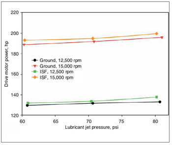
Figure 12—Effect of lubricant jet pressure on drive motor power required to rotate the entire test facility (˜200°F oil inlet temperature, 33% of maximum torque applied).
In Figures 13 and 14, the effects of lubricant inlet temperature are shown for drive motor power required (for the entire test stand) and temperature increase across the gearbox, respectively. The gears in this test were superfinished; the load on the system was 100% and the lubricant jet pressure was 80 psig. In Figure 13, by varying the inlet temperature from 160 to 250°F, the power required decreased approximately 10 hp. In Figure 14, the temperature differential between inlet and exit of the test gearbox resulted in a much lower temperature differential across the gearbox as the inlet temperature was increased.
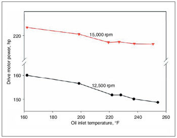
Figure 13—Effect of oil inlet temperature on drive motor power to rotate the entire test facility (superfinished gears, 80 psi lube jet pressure, 100% torque).
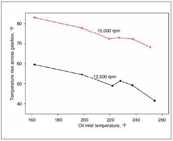
Figure 14—Effect of oil inlet temperature on the temperature rise across the test gearbox (superfinished gears, 80 psi lube jet pressure, 100% torque).
The last comparison to be made between the as-ground and superfinished gears will be made in Figure 15. The data provided in this figure show the drive motor power to rotate the test rig at two different speeds (12,500 and 15,000 rpm) and three different bull gear torques (~33, 67 and 100%). A linear behavior is shown with increasing load at constant speed. From this figure it can be concluded that improving the surface finish of these components had no efficiency benefits, as the data were nearly identical.
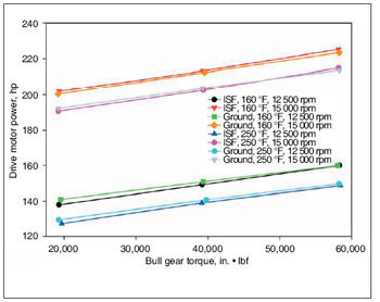
Figure 15—Comparison of the baseline (ground) to superfinished gears at two temperatures, two input shaft speeds and three load levels.
Discussion of Results. The question raised when reviewing the results of this study is “Why didn’t superfinishing improve the performance of this high-speed gear mesh?” To determine why no benefit was found, an analysis of the input –1st idler gear mesh was made to determine the lambda ratio (lubricant film thickness/composite surface roughness of the meshing gears). For the analysis, the bulk temperature (gear and lubricant) was assumed to be 230°F. In Figures 16 and 17, the results of the analysis are shown. In Figure 16, the input shaft speed is held constant at 15,000 rpm and the surface roughness and input torque are varied. Only for the case where the surface roughness is <12 µin. would there be a lambda ratio >1. In Figure 17, the torque was held constant at 100%, and the surface roughness and input shaft speed were varied. In this case, the lambda ratio could be reduced below one for all conditions if the shaft speed was reduced to a low enough level at the full power condition. Therefore, superfinishing of the parts did not take a system that was in the mixed elastohydrodynamic condition and move it to the fully flooded condition where the lambda ratio is <1. In most of the tests in this study, for both as-ground and superfinished tooth surface conditions, the lambda ratio was two or greater.
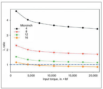
Figure 16—Effect of input torque on λ ratio for four different levels of surface finish at constant input shaft speed.
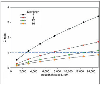
Figure 17—Effect of input shaft speed on λ ratio for four different levels of surface finish for constant torque.
Conclusions
For the results attained, the following conclusions can be made:
1. Superfinishing provided no measurable performance benefit to the high-speed gearing system under study. The film thickness to composite surface roughness was two or greater for most of the tests conducted.
2. Increasing lubricant inlet temperature provided the most beneficial effect to the performance of the drive system.
3. Thermocouple rakes and arrays installed in the test gearbox provided data that the fling-off temperatures vary with location across the face width of the gears, as well as the location within the gearbox where the temperatures were measured. The idler-idler gear meshes typically produced the highest rake and array temperatures measured in all tests.
4. The change in flow rate (due to lowering the lubricating jet pressure from 80 to 60 psig) had only a very minor effect on power loss.
References:
1. Kilmain, C., R. Murray and C. Huffman. “V–22 Drive System Description and Design Technologies,” American Helicopter Society 51st Annual Forum, May, 1995.
2. Handschuh, R. and C. Kilmain. “Preliminary Investigation of the Thermal Behavior of High-Speed Helical Gear Trains,” NASA/TM—2002-211336, ARL–TR–2661, March, 2002.
3. Handschuh, R. and C. Kilmain. “Efficiency of High-Speed Helical Gear Trains,” NASA/TM—2003-212222, ARL– TR–2968, April, 2003.
4. Handschuh, R. and C. Kilmain. “Preliminary Comparison of Experimental and Analytical Efficiency Results of High-Speed Helical Gear Trains,” ASME 2003 Design Engineering Technical Conference, September, 2003, Chicago, IL.
5. Handschuh, R. and C. Kilmain. “Experimental Study of the Influence of Speed and Load on Thermal Behavior of High-Speed Helical Gear Trains,” NASA/TM—2005213632, ARL–TR–3488, July, 2005.
6. Handschuh, R. and C. Kilmain. “Operational Influence on Thermal Behavior of High-Speed Helical Gear Trains,” NASA/TM—2006-214344, ARL–TR–3969, November, 2006.
7. Krantz, T., H. Alanou, H. Evans and R. Snidle. “Surface Fatigue Lives of Case-Carburized Gears With an Improved Surface Finish,” NASA/TM—2000-210044, ARL–TR–2170, DETC2000/PTG–14373, April, 2000.
8. Krantz, T. “The Influence of Roughness on Gear Surface Fatigue,” NASA/TM—2005-213958, ARL–TR–3134, October, 2005.
Dr. Robert F. Handschuh has since 1982 been an aerospace engineer in the U.S. Army Research Laboratory, vehicle technology directorate, at the NASA Glenn Research Center in Cleveland. From 1984 to date, he has applied his expertise to power transmission, with a focus on experimental and analytical studies of planetary, spiral-bevel, face and high-speed gearing. The author of well over 100 technical papers, he holds a patent on a gas turbine engine shroud seal, and two patents on gas turbine bearing coking and minimization removal. An ASME fellow, he also serves on its power transmission and gearing committee.
R. Ehinger is a senior engineer in the drive system design group, and has been with Bell Helicopter-Textron since 2004. He received his bachelor’s degree in mechanical engineering from Texas A&M University in 2003 while working summers as a draftsman and machinist for the oil industry. In addition, Mr. Ehinger is working on a master’s degree in engineering management at Southern Methodist University. As project area lead for drive system research, he is responsible for the strategic planning and development of technology in areas such as materials, lubrication, configuration, efficiency and manufacturing. He is author of the AHS paper “Evaluation of Isotropic Superfinishing on a Bell Helicopter Model 427 Main Rotor Gearbox,” and is co-author of “Application and Configuration Issues of Resin Transfer Molded Composite Transmission Housings—A Program Overview.”
Charles Kilmain is the chief of tiltrotor drive system design and research with Bell Helicopter-Textron, where he has served since 1985. Kilmain received a BSME from the University of Maryland in 1985. His experience includes layout, detailed design and development testing for the V-22 proprotor gearbox (FSD); lead engineer on the V-22 proprotor gearbox (EMD); and lead engineer on the BA609 commercial tiltrotor midwing gearbox and interconnect shafting system. Kilmain is also the lead engineer for Bell’s heavy lift rotorcraft drive system configuration and has served as drive system research project engineer for drive system research programs. Research programs include Advanced Rotorcraft Transmission II; H1 Composite Top Case; Advanced Gear Technology and High-Speed Helical Gear Loss-Of-Lube Evaluation at NASA Glenn. Publications include “V-22 Drive System Description and Design,” and “Composite Applications for Rotorcraft Drive System Housings.” He is also co-author of several works on thermal efficiency of high-speed helical gear trains and presentations on Advanced Rotorcraft Transmission II.