Optical Metrology for Evaluating Gear Noise
Klingelnberg looks at changing demands in automotive applications
When electric drives are used in vehicles, the masking effect of an internal combustion engine disappears, allowing the noise behavior of the transmission to take center stage. At the same time, peak power and torque increase, engine speeds increase, and power must be transferred optimally in both directions due to the regenerative braking system. Conventional design parameters remain important, however: The build space is limited, durability must not be compromised, and the product must still be cost-efficient. Optical metrology as part of a hybrid measurement concept helps to overcome all these challenges.
In the automotive industry in particular, the demands placed on transmissions and thus also on gears have changed dramatically. When electric motors are used with increasing frequency, the design criteria and requirements for gear and transmission designs change. This applies to both hybrid drive concepts and pure-electric vehicles—in fact, the choice of energy source (battery or fuel cell, for example) hardly plays any role at all for the transmission. In addition to production machines, such developments call for even more precise, modern metrology.
The first question that is frequently asked is how accurate a measurement must be. A highly accurate measurement is often relatively slow—and thus expensive—putting it in direct conflict with modern gear measurement systems, with their fast cycle times on the shop floor and high-cost pressure. At the same time, today’s evaluations, such as those used for noise analysis, require an extended measurement scope compared to conventional gear measurement. It is therefore important to know exactly what needs to be measured, and what the measuring equipment needs to be capable of doing. The capability of the measuring equipment is one of the factors that determines whether the end result is a capable process.
Capable Measuring Equipment Theory
To evaluate the capability of measuring equipment, two things are required: a target value in the form of a tolerance and a method to verify whether this tolerance can be reliably measured. The first reference for tolerances (cylindrical gears) is DIN ISO 1328, where formulas for geometry- and type-dependent tolerances for different quality classes can be found. Typical quality classes in the automotive sector range from Class 4 to Class 6 with corresponding values for numerous deviation types in the one- to two-digit-micrometer range. The method usually chosen is a capability analysis or measurement system analysis (Type 1 study), in which the repeatability (standard deviation or Cg value) and the systematic deviation (Cgk value) are determined on a certified artifact over a study range of at least 25 (typically 50) measurements. The Cg value for such an analysis is defined as follows:
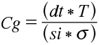
where T is the drawing tolerance (as specified in DIN ISO 1328) and dt is a tolerance factor (typically 0.2, corresponding to 20 percent). si is a sigma interval factor that defines the permissible process variation via the number of standard deviations: Typically, this is 4 σ or 6 σ, ≈ 95 percent or ≈ 99 percent, respectively. Cgk is broadly equivalent to Cg but is extended to include an average deviation from a reference value. It is defined as follows: