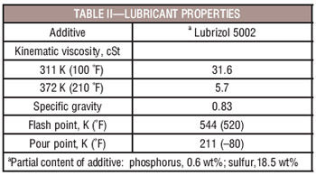
Test Procedure for Surface Fatigue Testing. The gears were lubricated with a single batch of synthetic paraffinic oil. Physical properties of this lubricant are summarized in Table II. Five percent of extreme pressure additive, with partial contents including phosphorus and sulfur, were added to the lubricant. This lubricant has been used extensively for gear fatigue testing in the NASA Glenn spur gear fatigue rigs. For example, Krantz (Ref. 6) reported results of 146 tests using this same oil (termed “NASA standard” in the referenced article) to evaluate the surface fatigue lives of AISI 9310 steel gears. The oil and additive mixture used in this work is similar to 5-centistoke oils used for helicopter main-rotor gearboxes.
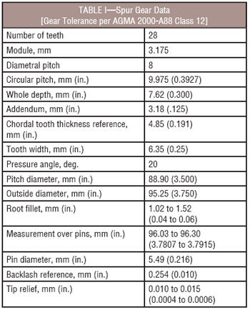
The test gears were run with the tooth faces offset by a nominal 3.3 mm (0.130 in.) to give a surface load width on the gear face of 3.0 mm (0.118 in). The actual tooth face offset for each test is based on the measured face width of the test specimen, and the offset is verified upon installation using a depth gage. The nominal 0.13 mm (0.005 in.) radius edge break is allowed for to calculate load intensity. All tests were run-in at a load (normal to the pitch circle) per unit width of 123 N/mm (700 lb./in.) for 1 hour. The load was then increased to 587 N/mm (3,350 lb./in.), which resulted in a 1.72-GPa (250-ksi) pitch-line maximum Hertz stress. At the pitch-line load, the tooth bending stress was 0.21 GPa (30 ksi) if plain bending was assumed. However, because there was an offset load, there was an additional stress imposed on the tooth bending stress. The combined effects of the bending and torsional moments yield a maximum stress of 0.26 GPa (37 ksi). The effects of tip relief and dynamic load were not considered for the calculation of stresses. The dynamic tooth forces on the gear teeth for test gears made to geometry specifications consistent with the present work have been previously reported (Ref. 6).
The gears were tested at 10,000 rpm, which gave a pitch-line velocity of 46.5 m/s (9,154 ft./min.). Inlet and outlet oil temperatures were continuously monitored. Lubricant was cooled and supplied to the inlet of the gear mesh. The lubricant outlet temperature was recorded and observed to have been maintained at 349±5 K (169±7 °F) once the rig was running and the temperatures were stabilized. The tests ran continuously (24 hr/day) until a vibration detection transducer automatically stopped the rig. The transducer is located on the gearbox adjacent to the test gears. Also, the surfaces of the teeth on the driven gear were inspected at regular intervals (normally not exceeding 50 million cycles between inspections) to verify the absence of surface fatigue. The lubricant was circulated through a 5 µm (200 µin.) nominal fiberglass filter to remove wear particles. For each test, 3.8 liters (1 gal) of lubricant were used. Six identical test rigs were used in this work. The pairing of gear samples and the run order was done randomly to minimize rig-to-rig and temporal differences.
The film thickness at the pitch point for the operating conditions of the surface fatigue testing was calculated using the computer program Extern. The computing tool is an implementation of the methods of References 7 and 8. For the purposes of the calculation, the gear surface temperature was assumed to be equal to the average of the oil inlet and outlet temperatures. Using the stated assumptions, the calculated pitch-line film thickness is 0.54 µm (21 µin.)
Test Procedure for Single-Tooth Bending Fatigue Testing. The gear test assembly is depicted in Figure 5. The gear test specimen is press fit on a shaft in the fixture’s casing. The test assembly was designed to conduct tests on gear teeth in sets of three. This approach was adopted in part to provide the necessary clearance for the two load rods. To permit access to the gear tooth to be tested, several teeth nearby needed to be removed. Teeth were removed using the Electrode Discharge Machining (EDM) process. The upper load rod contacts the reaction gear tooth near the root of the tooth. In contrast, the lower load rod contacts the test gear tooth at the highest point of single-tooth contact. Adopting this approach, highest bending stresses are introduced into the test gear tooth and the location of fatigue failure is predetermined with a high degree of confidence. The rotational orientation of the test gear is precisely established using setup tooling. The rod that loads the test tooth at the highest point of single-tooth contact is representative of a rack gear (flat profile or infinite radius of curvature) contacting the test tooth.
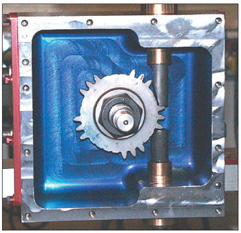
Figure 5—Test gear installed in test fixture, cover removed for photograph.
A check of the fixture alignment was made using machinists dye (bluing) applied to the gear tooth profile prior to testing. The dye removal created by the load rod contact areas gave a clear indication that uniform load distributions on both gear teeth had been achieved. The contact pattern procedure was followed in all tests with excellent results.
The single-tooth bending tests of this study were conducted using unidirectional loading. Testing was done in load control. The gear was positioned to provide load on the test tooth at the theoretical highest point of single-tooth contact for the case of the test gear mating with an identical gear at the standard center distance (radius of 44.30 mm, or 1.774 in.). The load is cycled from a small, minimum load to the maximum load desired for the given fatigue test. The load range was maintained at a constant value throughout the test. Loading was cycled at 0.5 Hz using a sinusoidal waveform. Crack initiation was defined to occur when the loading rod stroke increased approximately 2% (~ 0.0002 in. change) relative to the stroke for the gear tooth at test initiation.
Results and Discussion
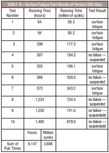
Surface Fatigue Test Results. Surface fatigue testing was completed on a set of gears manufactured from Ferrium C69 steel. The set of gears was case-carburized and ground. The test conditions were a load per unit width of 587 N/mm (3,350 lb./in.), which resulted in a 1.72-GPa (250-ksi) pitch-line maximum Hertz stress. For purposes of this work, failure was defined as one or more visible spalls or pits that can also be detected by tracing over the pit with a sharp stylus. The visual appearance of the surface fatigue (Figure 6) was typical of other alloys tested in the same conditions. The gears were qualitatively judged to have good wear resistance. Results of the surface fatigue testing are summarized in Table III. Ten gear pair surfaces were tested. Five of the tests resulted in surface fatigue failures. The other five tests resulted in no surface fatigue and no impending indication of fatigue, and therefore can be considered as suspended tests.
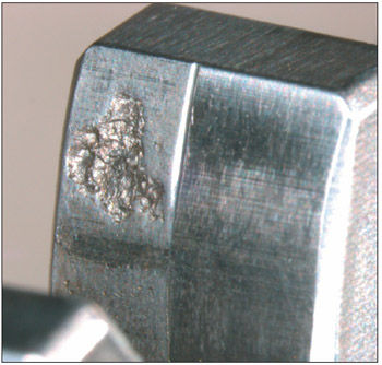
Figure 6—Typical surface fatigue failure of the Ferrium C69 alloy.
The experiments conducted were accelerated life tests. That is, for a helicopter application, the gears would operate at stress levels less than the stresses used for testing. Such an approach is used to economically produce surface fatigue data. To evaluate the significance of the surface fatigue test results, one can compare the results to past work done using different gear alloys but identical gear geometry specifications and test procedures. Often, fatigue test results are compared on the basis of the predicted ten-percent lives (Refs. 1, 5, 10). The present work comprised ten tests with five of the ten tests resulting in surface fatigue. An estimate of the ten-percent life from such a limited dataset provides for estimates with large statistical confidence intervals (Ref. 6). Therefore, for the present work, comparisons are made using estimates of the median (50 percent) lives. The distribution of fatigue life was modeled as a two-parameter Weibull distribution. The median life estimate was calculated by the method of Johnson (Ref. 9).
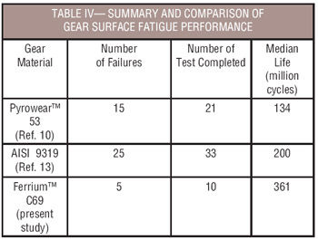
Krantz (Ref. 6) provided a summary of 18 sets of experiments conducted using test methods consistent with the present work, gears made from AISI 9310 steel, and various lubricants and surface treatments. Results of tests conducted using test methods consistent with the present work and using gears made from Pyrowear 53 steel have also been reported (Refs. 10, 11). Some of the referenced data are for gears having shot peening or superfinishing treatments to improve the surface fatigue lives. To provide the most direct comparison with the present study, the data for “standard-ground finished” gears (no shot peening or superfinishing of the contacting surfaces) were selected as the most appropriate baseline. Table IV provides a comparison of the results of the present study with the results of the previous works (Refs. 10, 13). The data of Table IV are the results for the best-performing sets of “standard-ground finished” gears made from the noted alloys and tested to date on the same gear test apparatus using the same test method. The estimated surface fatigue lives (median values) of Pyrowear 53, AISI 9310 and Ferrium C69 are 134, 200, and 361 million cycles, respectively. For contact stress of 1.7 GPa, as used in the present testing, 40 of the 54 tests of the baseline alloys exhibited surface fatigue before 300 million cycles. For the Ferrium C69 alloy, five of the 10 tests exceeded 300 million cycles without surface fatigue.
Bending Fatigue Test Results. Single-tooth bending fatigue testing was completed on a set of gears manufactured from Ferrium C69 steel. The set of gears was case-carburized and ground. Testing was done using unidirectional loading and load control. Testing was done until crack initiation occurred or, in some cases at the lowest levels of test load, tests were suspending with no cracks initiated. Crack initiation was defined to occur when the loading rod stroke increased approximately 2% (~ 0.0002 in. change) relative to the stroke for the gear tooth at test initiation.
Prior to conducting single-tooth bending tests on the test gears of the present study, tests had been conducted on gears made from AISI 9310 alloy (Ref. 12). In the previous work, crack initiation was defined to occur when the loading rod stroke increased approximately 2% (~ 0.0002 in. change) relative to the stroke for the gear tooth at test initiation. At this point a crack would be initiated with a size on the order of the case depth. Additional test cycles could then be applied to the AISI 9310 gears and stable crack growth would occur until the test was terminated with a crack of length 30~50% of the distance across the base of the tooth. The tooth with the fatigue crack could then be removed using a single impact load in order to observe the fracture surface. The present testing was initiated with the same definition of crack initiation in mind. However, it was observed that complete failure (removal of the tooth from the rim) occurred before a crack could grow in a stable manner to even the small size that would increase the loading stoke by 2%. Figure 7 provides examples of failed gear teeth. The differing crack trajectories illustrate the relatively brittle nature of the gear teeth made from the new alloy as compared to the baseline AISI 9310 gear teeth.
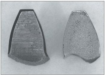
Figure 7—Typical failed teeth after single-tooth bending fatigue testing for Ferrium C69 (left) and AISI 9310 (right) steel alloys.
To express the intensity of the test loads, the maximum principal tensile stress in the fillet region was calculated using linear elastic finite element analysis (Ref. 12). The finite element model geometries were adjusted to closely match the actual manufactured tooth geometries as recorded using a digital microscope, including actual tooth thickness and root-fillet geometry details. The resulting stress owing to the applied load is reported herein as a stress index. It is appropriate to report test condition as a stress index since this test stress does not take into account the residual stress that exists in the case-carburized hardened gears. Furthermore, the reported test stress owing to the applied load was calculated assuming linear elasticity, and so plasticity and nonlinear effects were not considered. The relationships of crack initiation life as a function of the stress index for the present work and previous work (Ref. 12) are depicted in Figure 8 as a semi-logarithmic plot. For loads resulting in crack initiation within the cycle range 100–100,000 cycles, it is clear that AISI 9310 has superior performance relative to the new alloy. Also, the AISI 9310 exhibited excellent toughness, having stable crack growth, but the new alloy exhibited brittle behavior with fast fracture occurring over essentially the full base of the tooth in all cases. For consideration as an alloy for safety-critical gear applications such as main rotor transmissions of helicopters, such brittle behavior is unacceptable. It should be noted that S-N curves for case-carburized gear teeth are often depicted as two lines on semi-logarithmic axes, one line in the region of (100 cycles~5 million cycles) and another line for the very high cycle regime (> ~500 million cycles). The behavior of the new alloy in the very high cycle regime could not be investigated in a reasonable amount of time using the test method of this project (0.5 Hz loading frequency). Note that four tests of the Ferrium C69 steel were suspended with no failure after cycle counts approaching 1 million cycles. The trends of all the data from Figure 8 suggest that the Ferrium C69 gear might exhibit good performance against crack initiation in the very-high cycle regime.
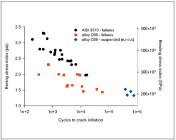
Figure 8—Results of single-tooth bending fatigue testing of Ferrium C69 and AISI 9310 steel gears (data for AISI 9310 are from Ref. 12).
(Editors note: This work provides some data on the behavior of the newly developed alloy. The selection of an alloy for a particular application of course requires the consideration of many properties, and the present work was not a full evaluation. For example, the scoring resistance of the new alloy was not investigated. The fracture toughness of the gear tooth is very important for safety-critical aviation gearing, and the fracture toughness was not evaluated in this study. This study quantified some performance characteristics of the new alloy and has provided guidance for the design and development of next-generation gear steels.)
Summary
Gears made from steel alloy Ferrium C69 were tested using the NASA Glenn Research Center’s gear test apparatus. Results of the present study were compared to past works done using the same test apparatus and test methods.
For surface fatigue testing, the present results were compared to previous works testing AISI 9310 and Pyrowear 53 (AMS 6308B), two alloys used in production today as aircraft steels. Surface fatigue testing was done at a contact stress of 1.7 GPa (250 ksi). The Ferrium C69 provided for better surface fatigue performance relative to the production alloys.
For bending fatigue testing, the present results were compared to previous works testing AISI 9310. Testing was completed using the single-tooth bending method, load control and a crack initiation definition of a 2% increase in the test load stroke relative to the stroke of the initial loadings. Tests were conducted at loads that generally resulted in crack initiation in the cycle range 100 cycles to 1 million cycles. The resistance of the Ferrium C69 gears to crack initiation was less than the baseline AISI 9310 gears. The new alloy exhibited relatively brittle behavior with fast fracture occurring across essentially the full base of the tooth while the AISI 9310 test gears exhibited stable crack growth for cracks extending up to 50% of the tooth base.
This study quantified some performance characteristics of the new alloy and has provided guidance for the design and development of next-generation gear steels.
References
1. Zaretsky, E. “Tribology for Aerospace Applications.” STLE SP–37, 1997.
2. Beswick, J. “Bearing Steel Technology.” ASTM STP 1419, 2002.
3. Zaretsky, E., R. Parker and W. Anderson. “Effect of Component Differential Hardness on Rolling-Contact Fatigue and Load Capacity.” NASA TN D-2640, 1965.
4. Rakhit, A. Heat Treatment of Gears, ASM International, 2000.
5. Townsend, D., J. Chevalier and E. Zaretsky. “Pitting Fatigue Characteristics of AISI M 50 and Super Nitralloy Spur Gears,” NASA TN D–7261, 1973.
6. Krantz, T. “The Influence of Roughness on Gear Surface Fatigue,” Ph.D. Thesis, Case Western Reserve University, 2002.
7. Anderson, N., S. Lowenthal and J. Black. “An Analytical Method to Predict Efficiency of Aircraft Gearboxes,” NASA TM–83716, AIAA Paper 84–1500, 1984.
8. Anderson, N., and S. Lowenthal. “Spur-Gear-System Efficiency at Part and Full Load,” NASA TP–1622, 1980.
9. Johnson, L. The Statistical Treatment of Fatigue Experiments, Elsevier Publishing Co., 1964.
10. Townsend, D. “Surface Fatigue Life and Failure Characteristics of EX53, CBS 1000M, and AISI 9310 Gear Materials,” NASA TP 2513, 1985.
11. Niskanen, P., A. Manesh and R. Morgan. “Reducing Wear with Superfinish Technology,” AMPTIAC Quarterly, Vol. 7, No. 1, 2003.
12. Handschuh, R., T. Krantz, B. Lerch, and C. Burke. “Investigation of Low-Cycle Bending Fatigue of AISI 9310 Steel Spur Gears,” DETC2007-34095, ASME IDETC/CIE 2007, September 4-7, 2007, Las Vegas, Nevada, USA.
13. Townsend, D. and E. Bamberger. “Surface Fatigue Life of Carburized and Hardened M50NiL and AISI 9310 Spur Gears and Rolling-Contact Test Bars,” NASA TM 101979, AVSCOM TR 89-C-011, 1989.
Trade names or manufacturers’ names are used in this report for identification only. This usage does not constitute an official endorsement, either expressed or implied, by the National Aeronautics and Space Administration or by the Army Research Laboratory.
This article was originally published by the American Society of Mechanical Engineers (ASME) for the ASME 2007 International Design Engineering Technical Conferences & Computers and Information in Engineering Conference. It is republished here with the permission of ASME.
Dr. Timothy Krantz has been employed by the Army Research Laboratory Vehicle Technology Directorate since 1987. During this time, he’s worked in cooperation with the NASA Glenn Research Center’s Mechanical Components Branch. He works jointly with Army and NASA staff to advance mechanical component and system technology. His research interests include all aspects of drive systems including gear and bearing strength; fatigue and durability; gear manufacturing processes; gear noise and vibration; tribology; and condition-based maintenance. He is a member of the ASME Power Transmission and Gearing Committee.
Brian Tufts serves as manager-business development at QuesTek Innovations and is an expert in the design and use of high-strength steels. Tufts holds both an MS in materials science engineering from Northwestern University and an MBA in marketing/strategy from the Kellogg School of Management. His current work involves emerging high-strength alloys for use in aerospace applications, specifically for powertrain gearing and in landing gear. QuesTek Innovations LLC is a materials solutions company that designs and licenses proprietary alloys. Tufts has served as principal investigator on multiple design contracts and owns specific expertise in case-carburized gear and bearing steels.