
Polish Grinding of Gears
Surface quality and efficiency go hand in hand
This article introduces the process of polish grinding of gears. Improved surface quality increases the overall efficiency of gearboxes, resulting in reduced friction and torque loss, higher power density, and noise-optimized gears (lower NVH); all these factors are highly relevant, especially for electric drives. When Reishauer developed polish grinding in 2012, the process aimed to improve the efficiency of ICE engine transmissions, and the set goals were easy to achieve. Today, in 2023, the situation is dramatically different. While an ICE engine operates at around 3,000 rpm and supplies acoustic masking of the gear noise, EV drivetrains feature up to 20,000 rpm and offer no such masking.
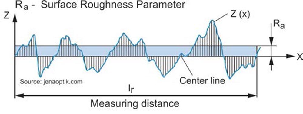
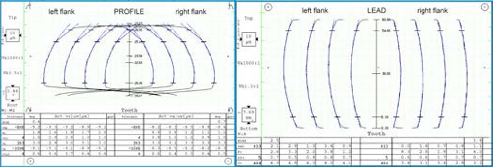
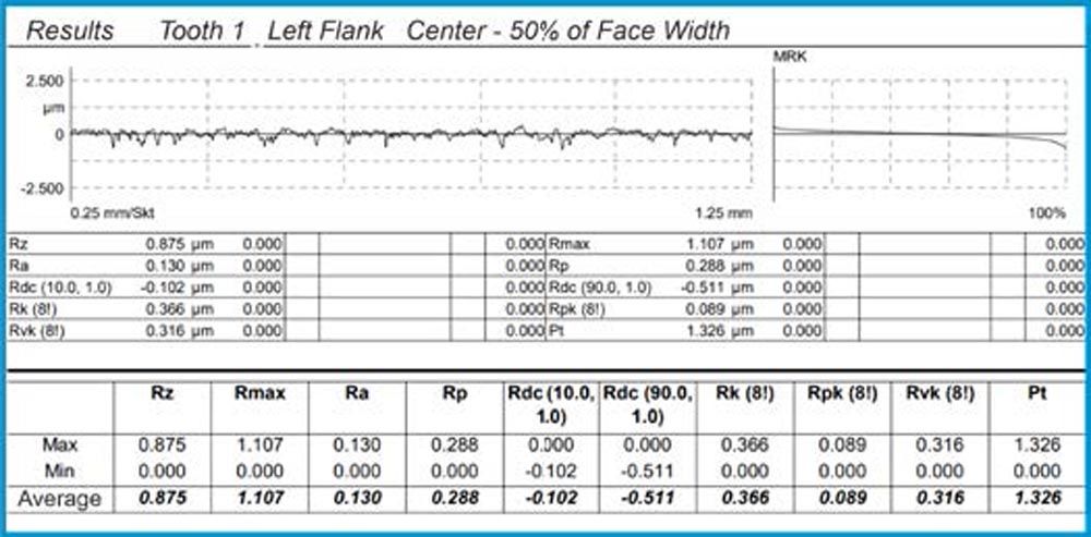
For this reason, EV gears must run substantially quieter. Furthermore, both left and gear flanks must perform identically for acceleration and deceleration due to regenerative braking. When looking at the surface texture, we must distinguish between roughness, waviness, and form. Any of these parameters can influence the performance of a gear. Polish grinding can only influence the roughness, not waviness or form. The grinding process must control form errors and waviness before polishing takes place. However, the continuous generating gear grinding process has proven to supply excellent quality in form, waviness, and pitch. Continuous generating gear grinding delivers a surface roughness of around Ra 0.3 µm, which has to be reduced by a subsequent polish grinding stroke. Let’s take a moment to ponder the term surface roughness:
“It’s common to hear ‘surface roughness’ described as a number that can be measured by a gauge. But describing surface texture with a number is a lot like describing a concert in decibels: Loudness is just part of the story. A rock band, an orchestra, and a chainsaw can all produce 100 decibels, but the full picture is much more complex and interesting.” (Ref. 1)
The Process
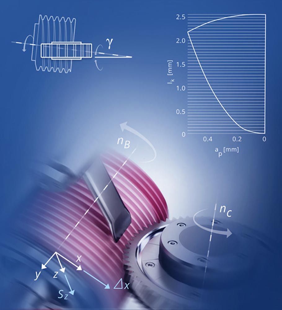
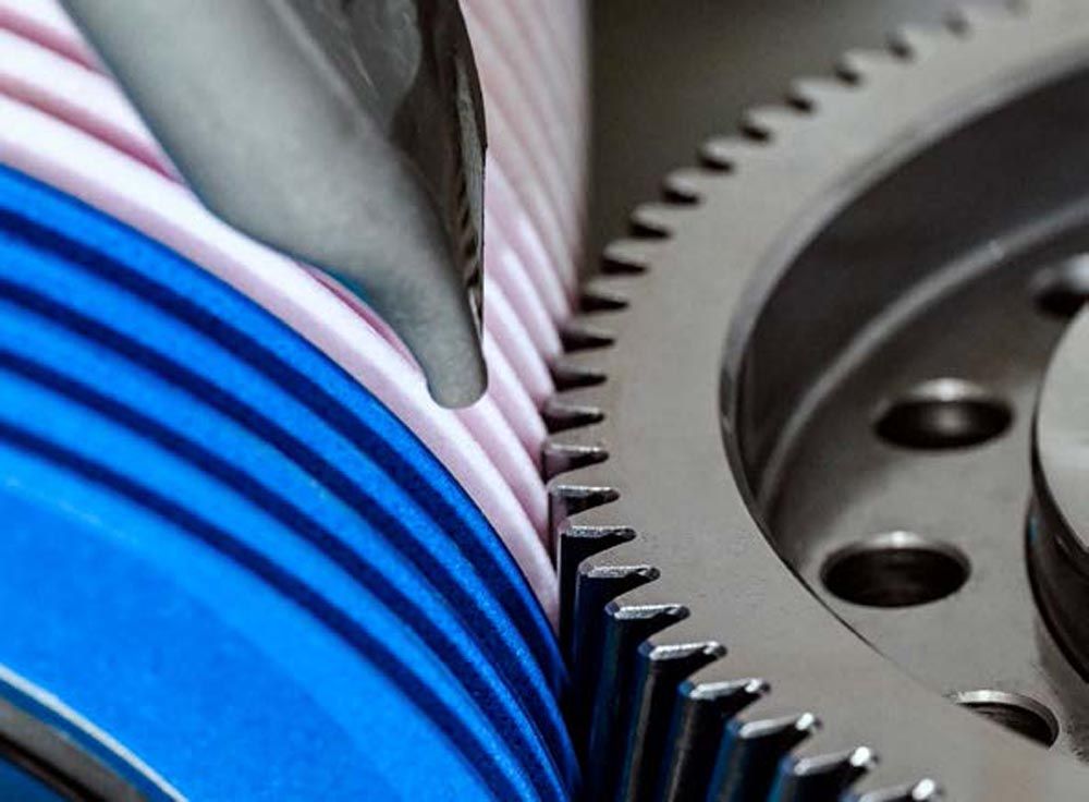
The basic technology for polishing grinding is continuous generating grinding. Based on a dressable grinding worm, this method has proven itself in terms of flexibility and high productivity. The kinematics of this process can be understood as a worm drive with rotational movements of the grinding worm and the workpiece (nB and nc), see Figure 2, with additional abrasive machining movements consisting of an infeed X, vertical feed Z, and lateral shift movement Y. The interaction of parameters creates a “contact zone.” The contact zone comprises a contact length lk, contact width ap, and contact depth ae.