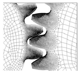
The deflection of the loaded tooth on the plastic driven gear is the cause of this skewed load share curve. As the loaded tooth is deflected, the rotational angle of meshing is moved out of phase, thus causing both preliminary contact by the next tooth entering mesh and prolonged contact at the end of mesh by the preceding tooth. That preceding tooth is being unloaded and is straightening back to its undeflected form (Fig. 5).
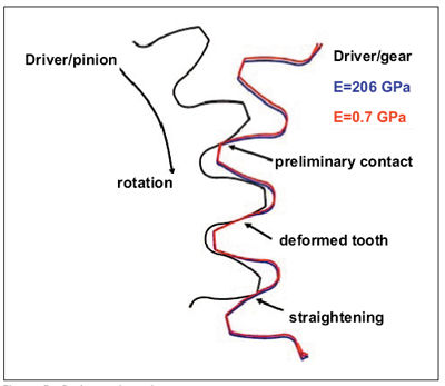
Figure 5—Deformed mesh.
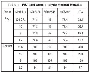
This increased contact—both entering and leaving mesh—will increase load sharing and thus lower the root stresses. Table 1 shows the results given by the FEA and semi-analytic methods. You can see the effect—as the modulus decreases, the FEA shows the actual stress decrease. The difference between the theoretical and actual (FEA) also becomes more significant. While most semi-analytic approaches allow no dependency for root bending stresses on modulus, the FEA shows there is indeed an effect of tooth deflection, which is indirectly dependent on modulus.
Fatigue tests correlation. Loads were selected by using FEA to get a reasonable number of cycles. The torques of four, five, six and eight Nm were run in the Berlin test rig. The gears were run constantly at 3,000 rpm and 140°C. Two materials were molded and tested—an unfilled PA46 and PEEK. Based on the torque levels, the root stresses were calculated using the FEA and ISO 6336. They are then being compared to tensile bar fatigue data. As you can see in Figure 6, the root stresses generated with FEA (labeled corrected) correlate well with the tensile specimens, while the ISO 6336 calculations exhibit much less of a correlation. Since the uncorrected or ISO 6336 equations yield apparently higher allowable stress values, caution in utilizing previously generated gear data must be used, as it may portray a false safety factor. This will depend on the loads, modulus based on temperature and resulting tooth deflection.
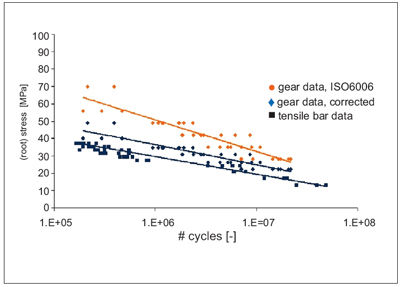
Figure 6—Fatigue results.
Tooth deflection vs. load and modulus. The effect of a lower material modulus has been shown to be that the tooth deflects under load. The modulus may be lower as a matter of material selection; for example, an elastomer vs. a thermoplastic. However, the modulus of thermoplastics is temperature- dependent and therefore may also be lower due to exposure to higher operating environment temperatures or increased frictionally generated temperatures. For example, 3 GPa is the modulus of an unfilled PA46 at 23°C, where at 140°C it has a modulus of 0.7 GPa. Modulus and load are reciprocally linked in this tooth deflection behavior. Stiffer materials will exhibit the same behavior as lower modulus materials when the corresponding load is increased. Figure 7 shows two identical results demonstrated with two different loads and moduli.
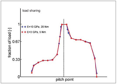
Figure 7—Load share vs. modulus and load.
Additional work. Up to this point, work has been done on a steel driver and plastic driven gear pair. Employing the noise and economical advantages of plastic gears often involves a plastic-on-plastic gear pair. The effects of tooth deflection can now be exhibited in both gears—both the driver and the driven. If we look at our load share curve again in Figure 8, we see that the curve now retains its symmetry. Also, the 1/3-2/3 portion of the curve now falls back on the “theoretical” values. The prolonged tooth contact—early and late in the roll angle—result in the load share peaking at 2/3, not one.
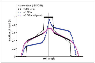
Figure 8—Load share plastic on steel vs. all-plastic.
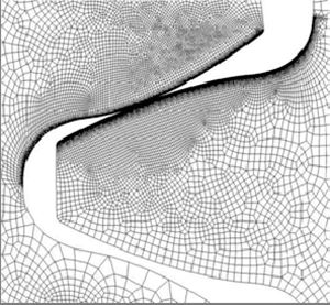
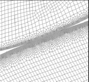
Figure 9 shows the increased contact ratio and the deviated contact path that result first from one plastic gear, and then increases as two plastic gears are used.
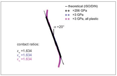
Figure 9—Contact path.
As previously pointed out, two unfilled materials were fatigue tested in injection-molded gears at the University of Berlin on the test rig. The two unfilled materials—PA46 and PEEK—were selected for their known applicability and use in the engine and under-the-hood automotive applications. Exposure to the oil lubrication and 140°C should not be a concern for either material. Figure 10 shows the fatigue results from these tests.
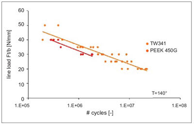
Figure 10—Fatigue of PA46 vs. PEEK.
PA46 shows impressive results on gear tests. PA46 is a highly crystalline polyamide in the same family with PA66 (nylon). It gains crystallinity of 70% vs. the 50% of PA66 or PA6 due to symmetrically repeating CH4, thus allowing more rapid and frequent coupling of the amide groups, CONH (see Figure 11). The speed of this crystallization allows this to happen, regardless of injection molding tooling temperatures.
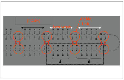
Figure 11—Molecular structure of PA46 and PA66.
This high crystalline nylon then sees an increase in nearly all properties important for gears. Wear is reduced while temperature capability is increased. Fatigue, especially in elevated temperature environments, is also dramatically improved (Figs. 12-14).
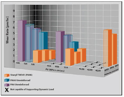
Figure 12—Wear and friction chart.
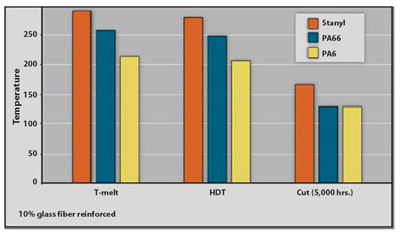
Figure 13—Thermal properties of PA46, PPA and PA66.
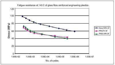
Figure 14—Fatigue of PA46, PPA and PA66.
Conclusions
Lab-generated tensile fatigue data can be used to predict plastic gear life. However, in order to utilize this data, it must be known what the actual root stresses in the plastic gear are.
If fatigue data are generated from actual gears—and that data is taken back to a typical S-N curve—knowing how the root stresses were calculated and if the stress values were corrected for tooth deflection are paramount.
Tooth deflection can cause large variances between the actual root stresses vs. theoretical. Therefore, gear tooth deflection must be analyzed and accounted for. This will require understanding the anticipated load, operating temperature plus frictionally induced heat and the corresponding material modulus at that cumulative temperature.
Steve Wasson received a Bachelors of Science in Mechanical Engineering from Michigan Technological University in 1988. He has spent 20 years in the creative design and application of plastic materials, and is the recipient of 15 patents. He has previously worked for Dow Chemical, BASF, and LNP/GE Plastics. He is currently at DSM Engineering Plastics developing gearing applications utilizing the high-performance Stanyl nylon 46 material.
Printed with permission of the copyright holder, the American Gear Manufacturers Association, 500 Montgomery Street, Suite 350, Alexandria, Virginia 22314-1560. Statements presented in this paper are those of the authors and may not represent the position or opinion of the American Gear Manufacturers Association.