


Thinking Outside the Box
Me, the New-CVT, the Multi-Ratio Gear and the 3D-involute
This is an odd piece to write, but probably necessary as I have created a storm around me. I am not an engineer and I am little more than a novice at gearing, but I am also the one who has invented a new type of geared CVT (the New-CVT (patent pending)) and a new involute gear type (the multi-ratio gear (patent pending)) (see: new-cvt.com). Furthermore anyone delving into this new technology quickly finds a whole new way of doing gearing. So people are confused and asking how this is possible.
 The New-CVT (patent pending) is basically an input and output pinion intermeshing with a main gear. The alternating blue and bronze colours indicate different conical involute gears (also know as beveloid gears) stacked on top of each other, each next one with two teeth more than the latter. Both pinions can slide to any position independently without disengaging the main gear. The great number of possible combinations of the pinion positions is what results in the CVT like performance. Gear change does not require the main gear to slow down. In the example shown above the gear ratio ranges from 1:1 to 1:4 with a total of 21 unique gear ratios. See an animation of this example on new-cvt.com.
The short answer is that I think differently to most people, I see options and underlying problems that most people cannot see. The downside is that I can only do it my way, so I really tend to irritate people who like solutions presented to them in the usual way. I am a very odd duck in a flock of beautiful swans. My background might also be a factor in this. As a biologist I focus on the why, while engineers tend to focus on the how.
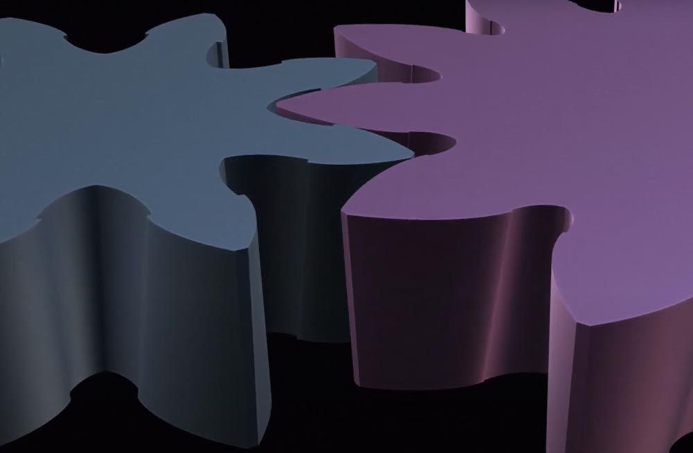
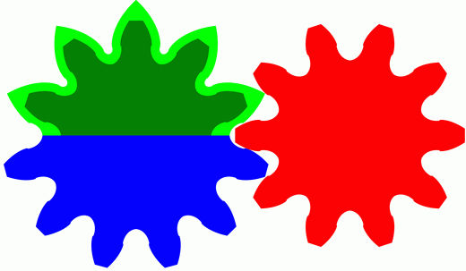 The multi-ratio gear (patent pending) (on the left) is an involute gear formed from two halves of donor gears with different amounts of teeth. Both halves intermesh perfectly with a pinion gear at the same distance between the axes. As it rotates the resulting gear ratio continuously cycles between two distinct values (gear ratio change is instant). In the New-CVT the conical gears are cut such that bordering conical gears effectively form multi-ratio gears between them. This is what makes gear change without disengaging or slowing down possible. See an animation of this example on new-cvt.com.
For example, conical involute gears, also known as beveloid gears, are not well defined in the literature. So I simply analysed this gear type down to its core fundamentals and found that it is actually the underlying shape of all involute gearing. It can be derived from a simple triangle (see the step by step graph bellow). And once one understands this, understanding all involute gearing becomes a lot easier.
 From the top left. A triangle (the diagonal line will become the intermeshing contact surface). A second triangle, identical to the first, rolled into cylinder. Many copies of the first triangle: positioned alike the first triangle, but with the size of each copy adjusted to match the height of the cylinder at the copy’s position around the cylinder. The many become infinite resulting in the 3D-involute shape. This structure underlies all involute gears, both 2D and 3D. Every cross-section along the axis of the cylinder shows a 2D involute curve emanating from a base circle. Basically the 3D-involute shape is nothing more than a straight line spiralling around and going up a cylinder at a constant speed. Most of the 3D-involute shape removed, with the remaining outer surface becoming a tooth face. What remained of the 3D-involute shape has been mirrored onto itself and the result copied six times around the base circle, the basic mathematical shape of a conical involute gear with six teeth. The end result. Note that the tips were cut off along the line of the triangle’s diagonal line at that position, this does not always need to be the case.
