[advertisement]
Technical Articles

February 27, 2025


Thomas Tallerico


Fatigue Fatigue Life Gear Life Materials Gear Steels Technical

Very High Cycle Fatigue Testing of AMS 6308 Steel

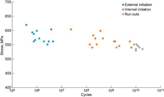
Lightweight and reliable gearboxes are required for helicopters and future electrical vertical take-off and landing aircraft. Mechanical gears in these applications experience more than 107 fatigue cycles over their operating life and between maintenance intervals. High-strength materials have been shown to fail due to fatigue past 107 stress cycles (Ref. 1). In this fatigue regime, the initiation point for the fatigue crack shifts from the surface to internal defects in the material, and the fatigue stress versus cycles curve has a different slope than the low-cycle fatigue regime (Refs. 1 to 4).

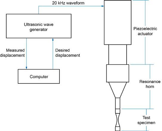
Traditional methods of predicting gear fatigue strength past 107 cycles rely on empirical extrapolation of the 107traditional fatigue strength of the material (Refs. 5 and 6). Extrapolation is used because data for gear steel strength past 107 cycles is rare due to the time and cost of testing to these high cycle counts using traditional fatigue testing methods. Ultrasonic fatigue testing is a material testing method that allows fatigue stress cycles to be generated in a specimen at 20 kHz. Correspondingly this method is practical for creating material fatigue data in the very high cycle fatigue regime (107 to 1010 cycles) (Ref. 1). Ultrasonic fatigue can lead to slightly different material fatigue strength predictions relative to predictions obtained with traditional fatigue test methods due to environmental effects, temperature rise, and the low stressed volume in the specimens (Ref. 7).

In this paper, ultrasonic fatigue testing results for “core hardened” AMS 6308 gear steel are presented. AMS 6308 is a gear and bearing steel with high tempering resistance and high hot hardness case targeted to high temperature applications (Ref. 8). The material tested in this paper is “core hardened” such that it is representative of gear tooth core material. Core hardening of the material is accomplished by masking the specimens and processing through the normal AMS 6308 case hardening heat treatment process. Core material strength is not directly applicable to the bending fatigue strength of gear teeth; however, understanding core material strength establishes a baseline for strength improvements achieved through case carburizing and could provide valuable information for the development of heat treatments for very high cycle fatigue strength. Since crack initiation shifts form the surface to internal location in the specimen in the very high cycle fatigue regime, achieving the right combination of case depth and residual stress could extend gear steel lifetimes. The results in this paper will be used to inform future ultrasonic AMS 6308 bending fatigue testing using the method described in Ref. 9 that is able to capture the effects of gear tooth heat treatment in a relevant bending fatigue stress environment.

Specimen Design

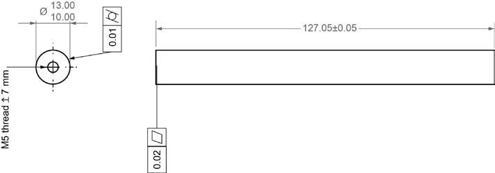
Past work by the author (Ref. 10), showed that using an axial ultrasonic fatigue specimen design as described in Reference 1 led to significant uncertainty of the stress state of the specimen since the ultrasonic horn used to excite the test specimen has an observable displacement noise level of ~0.05 μm. For the specimens in this paper, a new specimen design was carried out with the goal of reducing the uncertainty of the stress state to less than 1 percent. The dynamic modules of test specimens were measured using the method described in Ref. 1. A mean value for the measured material dynamic module based on seven specimens was 201.8 GPa. This measured value was used in all specimen modeling. Appendix A provides the specimen drawing (Figure 4) and specimen test results (Table I) for the dynamic modules of core hardened AMS 6308.

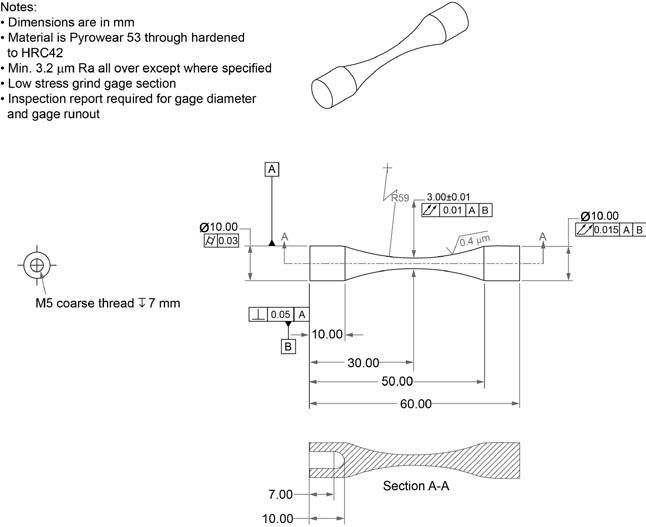
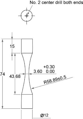
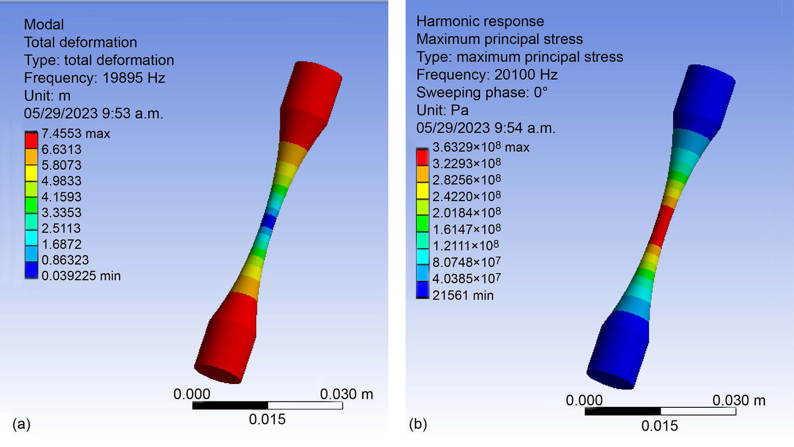
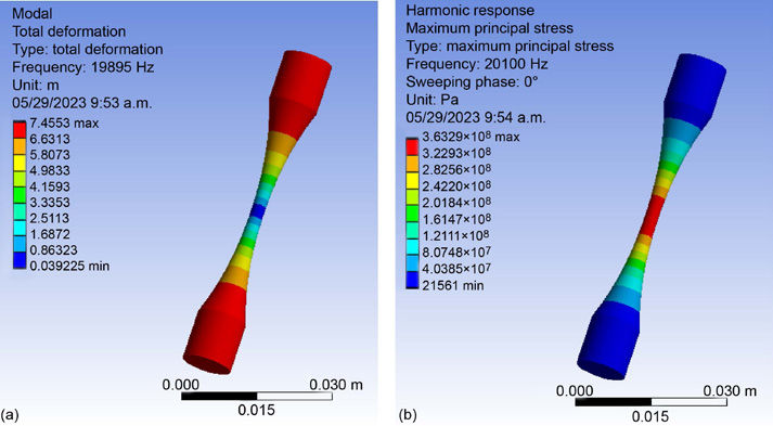
Appendix B provides the drawing for the developed AMS 6308 specimen (Figure 5). Minimum size end sections that are 10 mm long are used to reduce the slope of the stress versus displacement response of the specimen such that a 0.05 μm displacement uncertainty results in a stress uncertainty of ~1 MPa. Finite element analysis was used to achieve the specimen design. Figure 1 shows the FEA model results for specimen mode shape deformation and stress response.

Figure 1—Developed specimen FEA models. To the left shows modal analysis result. To the right shows harmonic response of the specimen at 20,100 Hz.

The specimen manufacturing was carried out in a four-step process:

  1. Premachining per drawing (Figure 6) in Appendix C.
  2. Heat treatment per process defined in Appendix D.
  3. Low-stress grind the gage section to desired dimensions.
  4. Final machine the part to length. Appendix B provides final part geometry (Figure 5).
Share and save:


This article appeared in the January/February 2025 issue.


Read PDF

[advertisement]

One error occurred during fabrication of the test specimens. The machining process used to final cut the parts to length led to scratches in the gauge section that resulted in premature fatigue failure of some preliminary specimens. After this observation of test results from preliminary specimens, hand polishing was used to improve the surface finish. However, the hand polishing was not a well-controlled process and should be noted as a possible source of error in the reported stress values in the “Testing Results” section.

Experimental Setup

The experimental setup for the testing is shown schematically in Figure 2. A piezoelectric actuator-based ultrasonic fatigue tester is used (Ref. 1). The tester consists of a data acquisition system, an ultrasonic wave generator, a piezoelectric actuator, and a resonance horn. The tester runs using displacement control. A specified displacement is set by the user and the ultrasonic wave generator controls the amplitude and frequency of the 20 kHz electrical wave it supplies to the piezo actuator to achieve the required displacement with minimal energy consumption. The piezo actuator produces a very small displacement sinusoidal wave at the frequency provided by the wave generator. The resonance horn attached to the end of the actuator is used to amplify the piezo actuator’s displacement to the target testing displacement. The resonance horn is designed to have a longitudinal mode at 20 kHz. If a specimen with a mode close to 20 kHz is attached to the end of the horn, the mode will be excited and stress/displacement cycles can be generated in that part corresponding to that mode shape of the specimen.

Figure 2—Schematic depiction of the ultrasonic fatigue rig.

Testing Results

Thirty-three specimens were produced and tested. The results in terms of stress and cycles are shown in Figure 3. Stress is reported as calculated form FEA using the measured dynamic modules of the steel of 201.8 GPa. Many points are shown to fail due to external defects at less than 107 cycles. These test points are believed to have been affected by the manufacturing process damaging their surfaces as discussed in the “Specimen Design” section. Regardless, in ultrasonic fatigue, fractures that occur at less than 107 cycles are typically significantly affected by heat generation and correspondingly should not be considered representative of material strength.

Figure 3—Peak specimen stress versus cycles to failure for core-hardened AMS 6308.

Twelve total specimens fractured in the range of 107 to 1010 cycles with initiation sites internal to the specimens. Fatigue strengths fell in the range of 550 MPa around the expected strength for core-hardened gear steels. Seven total specimens were run out to 1010 cycles at stresses slightly less than 550 MPa. The lowest fracture strength for a specimen before 1010 cycles was 540 MPa.

Conclusions

In this paper, ultrasonic fatigue testing results for core-hardened AMS 6308 were presented. Fatigue data was collected for the material in the range of 107 to 1010 fatigue cycles. Failure strengths were found to be in the range of 540 to 600 MPa for the stress cycle regime past 107 cycles. Seven total specimens were run out to 1010 cycles at stress levels around or below 540 MPa. These results are not directly applicable to the bending fatigue strength of AMS 6308 in case-carburized gear teeth. However, these results provide a baseline strength dataset for future bending fatigue tests of carburized ultrasonic bending fatigue specimens and could provide some valuable information for understanding gear failure or for refining heat treatments to accomplish long-life gears for aviation applications.

Appendix A—Dynamic Modules Testing Results

Figure 4—Dynamic modules testing specimen.
Specimen no.Length, mDensity, kg/m3Frequency, HzEd, Pa
11.27×10–17.85×1032.00×1042.05×1011
21.27×10–17.88×1031.98×1042.01×1011
31.28×10–17.87×1031.98×1042.01×1011
41.28×10–17.87×1031.98×1042.02×1011
51.27×10–17.88×1031.99×1042.02×1011
61.27×10–17.88×1031.98×1042.01×1011
71.27×10–17.87×1031.98×1042.01×1011

Table 1—Dynamic modules testing results.

Appendix B—Specimen Geometry

Figure 5—Final specimen geometry drawing.

Appendix C—Premachined Geometry

Figure 6—Preheat treatment and grinding specimen geometry.

Appendix D—Heat Treatment

  1. Copper plate specimens
  2. Heat to 1700 °F and hold 7 h in inert gas environment.
  3. Slod cool to room temperature.
  4. Reheat to 1675 °F and hold for 25 min in vacuum environment.
  5. 10 Bar N2 Gas Quench
  6. Refrigerate to –100 °F for 30 min
  7. Temperature at 400 °F for 2 + 2 h

NASA/TM-20240002274 9

References

  1. C. Bathias and P.C. Paris, Gigacycle Fatigue in Mechanical Practice, New York: Marcel Dekker, 2005.
  2. Y. Furuya, “A new model for predicting the gigacycle fatigue strength of high-strength steels,” Materials Science and Engineering: A, Vol. 743, pp. 445–452, 2019.
  3. Z. Lei, Y. Hong, J. Xie, C. Sun, and A. Zhao, “Effects of inclusion size and location on very-highcycle fatigue behavior for high strength steels,” Materials Science & Engineering: A, vol. 558, pp. 234–241, 2012.
  4. A. Sharma, M.C. Oh, and B. Ahn, “Recent Advances in Very High Cycle Fatigue Behavior of Metals and Alloys—A Review,” Metals, Vol. 10, No. 9, p. 1200, 2020.
  5. ANSI/AGMA, “Fundamental Rating Factors and Calculation Methods for Involute Spur and Helical Gear Teeth,” AGMA, 2010.
  6. J.J. Coy, D.P. Townsend, and E.V. Zaretsky, “Gearing,” NASA, Cleveland, 1985.
  7. Y. Hu, C. Sun, J. Xie, and Y. Hong, “Effects of Loading Frequency and Loading Type on High-Cycle and Very-High-Cycle Fatigue of a High-Strength Steel,” Materials, Vol. 11, No. 8, p. 1456, 2018.
  8. Carpenter Technology, “Cartech Pyrowear Allow 53 Data Sheet,” 8 September 2003. [Online]. Available: https://www.carpentertechnology.com/hubfs/7407324/Material%20Saftey%20Data %20Sheets/Pyrowear%2053.pdf. [Accessed 29 May 2023].
  9. Z. Cameron and T. Tallerico, “A Novel Ultrasonic Reversible Bending Fatigue Specimen for Simulated Gear Tooth Bending Fatigue,” in ASME International Design Engineering Technical Conferences & Computers and Information in Engineering Conference, Boston, 2023.
  10. T. Tallerico and Z. Cameron, “Ultrasonic Gear Steel Fatigue at NASA,” in ASME International Power Transmission and Gearing Conference, Anaheim, 2019.
  11. V. Kazymyrovych, “Very High Cycle Fatigue of Tool Steels,” Karlstad University, 2010.
This paper was originally published by NASA.