[advertisement]
Technical Articles

August 30, 2022


Robert Errichello


Micropitting

Nomenclature of Micropitting

Introduction

To understand a complicated subject, one needs to have a consistent and coherent system of nomenclature. It is the key to understanding the morphology and mechanism of micropitting. Unfortunately, it is typical for researchers to invent ambiguous terms for phenomena that are not well understood. It seems that the less we know about a failure mode, the more names we ascribe to it. This shortcoming is especially true for the complex phenomenon of micropitting.

Figure 1.jpg

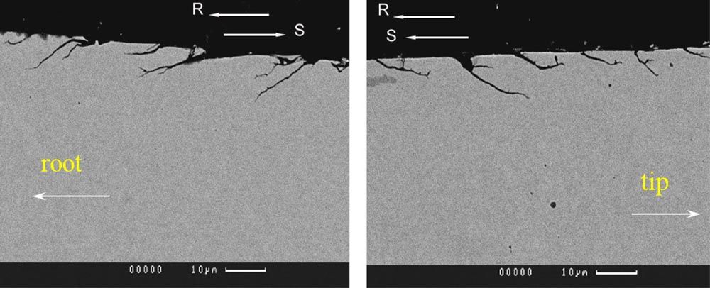
Figure 1 The image shows two polished metallurgical specimens cut transversely through gear tooth micropitting. The left shows the dedendum, and the right shows the addendum of the tooth of a driven gear. The vectors R and S indicate the rolling and sliding directions. Micropitting cracks start at the gear tooth surface and grow at a shallow angle (typically 10–30 degrees, but sometimes as steep as 45 degrees) to the surface. Image courtesy of Newcastle University.

Nomenclature

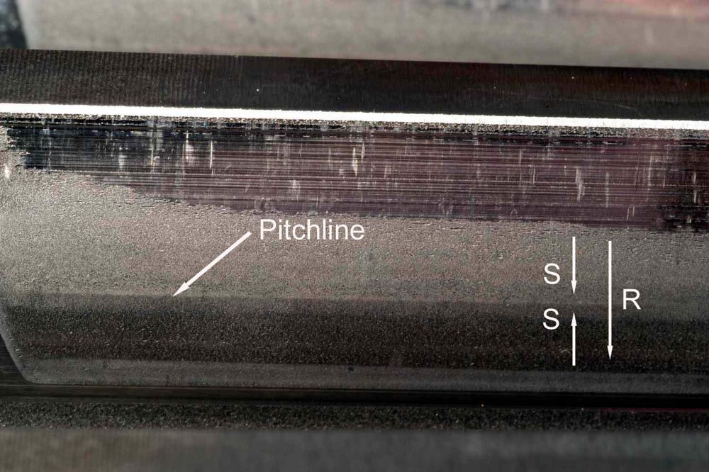
Tallian (Ref. 1) coined the phrase “surface distress,” which he later (Ref. 2) explained included micropitting. Tallian (Ref. 1) stated that the first sign of surface distress is a “burnished” appearance that is characterized by a “high gloss” of the metal and partial or total obliteration of the original finishing marks. He went on to say, “It is now believed that this appearance arises from plastic deformation of the asperities” and continued: “In a more advanced stage of this failure, small pits form on the burnished surface, which are at times aligned along ridges of the original asperities.”

In a later document (Ref. 2), Tallian introduced the term “glazing” when he stated that: “surface distress is attributed to asperity interactions causing plastic deformation (glazing) with subsequent microcracking and micropitting.”

In his Failure Atlas (Ref. 3), Tallian defined the early plastic flow stage of surface distress as glazing, and the later stage as micropitting. He describes a glazed surface as showing smoothing of asperity ridges into almost featureless flat areas (with valleys still discernible), possibly with some incidental wear marks or dents. In contrast, he states that under SEM magnification, microcracks opening to the surface may be visible in the glazed areas and describes a micropitted surface as appearing “frosted” to the unaided eye, possibly with barely visible black spots representing the micropits.

Incubation

Tallian’s early stage of surface distress is now confirmed to be the incubation stage for micropitting. In addition to Hertzian stress due to normal loading, sliding between gear teeth causes tractional forces that subject asperities to shear stresses. The first 104 to 106 cycles of stress occurring during run-in are an incubation period (Refs. 1, 12, 13) during which damage consists primarily of plastic deformation at asperities (Refs. 1–14). Spikes, Olver, and Macpherson (Ref. 12) give an excellent dissertation on the mechanism of the plastic deformation that occurs during the incubation period. Macroscopically, surfaces appear glazed or glossy (Ref. 12). Microscopically, surface asperities appear plastically deformed and original-machining marks might be partially or totally obliterated. Cyclic Hertzian and shear stresses accumulate plastic deformation on asperities and at shallow depths below asperities. The length of the incubation period depends on the relative hardness of the specimen and the mating components. Plastic flow produces tensile residual stresses (Refs. 10, 15) that increase the cyclic range of stresses that asperities are subjected to. With sufficient cycles, fatigue cracks initiate.

Nucleation and Growth

Share and save:


This article appeared in the August 2022 issue.


Read PDF

[advertisement]

After incubation, micropits rapidly nucleate, grow, and coalesce. Microscopy shows a continuously cracked surface. Periodic inspection of gear tooth profiles with a gear inspection machine discloses a steady rate of surface deterioration. The process of plastic deformation, followed by initiation, growth, and coalescence of cracks may be continuous (Refs. 11, 16, 17). Damage may be extensive after only 106 cycles (Refs. 4, 12, 16, 18, 19).

Micropitting begins when a fatigue crack grows from the gear tooth surface at an angle to the surface. A micropit forms when a branch crack connects the subsurface main crack with the surface and separates a small piece of material. The resulting micropit may be only 10 μm deep and not resolved by the unaided eye. Subsurface crack networks are usually much more extensive than would be implied from surface features.

The main crack undermines the surface by growing deeper and spreading in a fan shape. Micropits enlarge as the back edges of the micropits crack and small pieces of surface material are dislodged. Some particles are trapped in micropits, and others fall out of craters and entrain in the lubricant. Because debris from micropitting can be as small as 1 μm, it is unlikely filters will remove much (Ref. 11). The particles act as polishing agents and polishing wear is often found on gear teeth with micropitting, in areas between micropits, and in areas without micropitting.

Ground gear teeth with longitudinal scratches often have micropits along the edges of scratches (Refs. 11, 20). On the driver, micropits nucleate at the lower edges of addendum scratches, and at the upper edges of dedendum scratches (Ref. 20). Fan-shaped growth patterns cause adjacent micropits to coalesce and form continuously cracked edges that follow along grind scratches.

Morphology

To the unaided eye, micropitted gear teeth appear dull, etched, or stained with patches of gray. Micropitting is difficult to see under diffuse fluorescent lighting and is best observed with intense directional lighting. A flashlight with a concentrated beam held in the proper direction effectively illuminates micropitting. With intense lighting, micropitting may sparkle or appear speckled.

Scanning electron microscopy (SEM) shows the floor of a micropit crater slopes gently downward from its origin at the tooth surface. The floor has a rough surface typical of that caused by ductile fatigue crack propagation. A featheredge forms at the back of the crater due to the plastic flow of material over the crater rim. The featheredge appears white in SEM when it becomes charged with electrons. Material surrounding a micropit generally appears smooth and featureless unless abraded.

Metallurgical sections cut transversely through micropits show cracks start at or near the gear tooth surface and grow at a shallow angle (typically 10–30°, but sometimes as steep as 45°) to the surface, as shown in Figure 1 (Ref. 21). Like macropitting, micropitting cracks grow opposite the direction of sliding at the gear tooth surface (Refs. 10, 19–23). Because slide directions reverse as the pitchline is crossed, micropitting cracks grow in opposite directions above and below the pitchline. If micropitting grows across the pitchline, it makes the pitchline readily discernible because opposite inclinations of the bases of micropit craters scatter light in opposite directions above and below the pitchline (Refs. 11, 12, 24), as shown in Figure 2. When metallurgical sections are polished and lightly etched with nital, dark etching alterations (DEA) may be found at shallow depths below surface asperities (Refs. 20, 25, 26). DEA locate areas of microscale plastic deformation.

Nonpreferred Names for Micropitting

The micropitting phenomenon has been studied since early 1960 resulting in a vast literature. As is typical of many research subjects, micropitting has a long list of terms used to describe the failure mode. However, by general consensus, the preferred name is micropitting because it aptly describes both the appearance and mechanism. Therefore, to reduce confusion, and to improve communication, the following nonpreferred names are discouraged.

  • Asperity microcracking
  • Asperity microspalling
  • Asperity-scale distress
  • Asperity-scale fatigue
  • Delamination wear
  • Fatigue scoring
  • Fatigue wear
  • Flecking
  • Frosting
  • Glazing
  • Gray discoloration
  • Gray mottle
  • Gray staining
  • Gray stippiness
  • Microcracking
  • Microspalling
  • Peeling
  • Superficial cracking
  • Superficial pitting
  • Superficial spalling
  • Surface distress
  • Surface fatigue
  • Surface-initiated fatigue
  • Surface-origin spalling

Conclusions

Micropitting begins with an incubation period during which damage consists primarily of plastic deformation at asperities. Macroscopically, surfaces appear glazed or glossy. Microscopically, asperity ridges appear as almost featureless flat areas possibly with roughness valleys still discernible. The preferred nomenclature for the damage that occurs during the incubation period is glazing.

After incubation, micropits rapidly nucleate, grow, and coalesce. Macroscopically, a micropitted surface appears dull, etched, or stained with patches of gray. Microscopically, a dense field of micropits of various sizes can be seen. The preferred nomenclature for the damage that occurs during the micropitting period is micropitting.

[advertisement]

The root cause of micropitting is plastic deformation that occurs during the incubation period.

References

  1. Tallian, T.E., “On Competing Failure Modes in Rolling Contact,” ASLE Transactions, Vol. 10, No. 4, 1967, pp. 418–439.
  2. Tallian, T.E., “Dependence of Bearing Fatigue Life on Film Thickness to Surface Roughness Ratio,” ASLE Transactions, Vol. 18, No. 2, 1975, pp. 144–152.
  3. Tallian, T.E., “Failure Atlas for Hertz Contact Machine Elements,” 2nd Edition, ASME Press, 1999.
  4. Akamatsu, Y., “Peeling Damage Due to Rolling Contact Fatigue,” SAE Paper No. 891909, 1989, pp. 1–7.
  5. Bailey D.M., and Sayles R.S., “Effect of Roughness and Sliding Friction on Contact Stresses,” Trans ASME, J. Tribology, 113, 1991, pp. 729–738.
  6. Berthe, D., Flamand L., Foucher, D., and Godet, M., “Micropitting in Hertzian Contacts,” Trans ASME, J. Lubr. Technol., 102, 1980, pp. 478–489.
  7. Cheng, W., “A New Roughness Parameter Including Hardness and Contact Frequency Effects on Lubricated Rolling/Sliding Wear,” Tribology Transactions, Vol. 40, No. 3, 1997, pp. 486–492.
  8. Jacobson, B., “Rheology and Elastohydrodynamic Lubrication,” Elsevier, 1991.
  9. Nakajima, A., “Effect of Asperity Interacting Frequency on Surface Durability,” Int. Symp. On Gearing and Power Transmissions, Tokyo, Paper b-26, 1981, pp. 401–406.
  10. Olver, A.V., “Micropitting and Asperity Deformation,” In D. Dowson and M. Godet (eds.) Developments in Numerical and Experimental Methods Applied to Tribology, Proc. 10th Leeds-Lyon Symp. On Tribology, Sept. 1983, Butterworths, London, 1984, pp. 319–323.
  11. Shotter, B.A., “Micropitting: Its Characteristics and Implications on the Test Requirements of Gear Oils,” in Performance and Testing of Gear Oils and Transmission Fluids, Institute of Petroleum, 1981, pp. 53–60 and 320–323.
  12. Spikes, H.A., Olver, A.V., and Macpherson, P.B., “Wear in Rolling Contacts,” Wear, Vol. 112, No. 2, 1986, pp. 121–144.
  13. Tokuda M., Ito S., Muro H., and Oshima T., “Evaluation of Lubricants by an Accelerated Peeling Test,” in Rolling Contact Fatigue, Performance Testing of Lubricants,” Tourret, R. and Wright, E.P., eds. Heyden & Son Ltd. London, 1977, pp. 107–115.
  14. Zhou, R.S., “Surface Topography and Fatigue Life of Rolling Contact Bearings,” STLE Preprint No. 92-TC-5E-1, 1992, pp. 1–12.
  15. Chiu, Y.P., “The Mechanism of Bearing Surface Fatigue- Experiments and Theories,” Tribology Transactions, Vol. 40, No. 4, Oct. 1997, pp. 658–666.
  16. Ariura Y., Ueno T., and Nakanishi T., “An Investigation of Surface Failure of Surface-Hardened Gears by Scanning Electron Microscopy Observations,” Wear, 87, 1983, pp. 305–316.
  17. Flamand L., and Berthe, D., “A Brief Discussion of Different Forms of Wear Observed in Hertzian Contacts at Low Slide/Roll Ratios,” Surface Roughness Effects in Lubrication, Proc. 4th Leeds-Lyon Symp., Lyon, 1977, Mechanical Engineering Publications, London, 1978, pp. 239–242.
  18. Faure, L., “Micro Surface Damages on Tooth Flanks of Carburized Gears,” AGMA Paper No. 88 FTM 4, 1988, pp. 1–7.
  19. Webster, M.N., and Norbart C.J.J., “An Experimental Investigation of Micropitting Using a Roller Disk Machine,” Tribology Transactions, Vol. 38, No. 4, 1995, pp. 883–893.
  20. Hoeprich, M.R., “Analysis of Micropitting on Prototype Surface Fatigue Test Gears,” AGMA Paper No. 99FTM5, 1999, pp. 1–11.
  21. Hohn, B.R., Oster, P., and Emmert, S., “Micropitting in Case-Carburized Gears- FZG Micropitting Test,” VDI Berichte, NR. 1230, 1996, pp. 331–344.
  22. Graham, R.C., Olver, A.V., and Macpherson, P.B., “An Investigation into the Mechanisms of Pitting in High-Hardness Carburized Steels,” ASME Paper No. 80-C2/DET-118, 1980, pp. 1–7.
  23. MacPherson, P.B., “The Pitting Performance of Hardened Steels,” ASME Paper No. 77-DET-39, 1977, pp. 1–9.
  24. Strachan, D.C., Paul, D.M., and Bowen, A.W., “Investigation of a Laser Scattering Technique for the Study of Micropitting in Test Gears,” Wear, Vol. 72, 1981, pp. 219–236.
  25. Breen, D.H., “Physical and Analytical Modeling of Contact Fatigue Pits From Rolling/Sliding Tests,” AGMA Paper No. 87 FTM 8, 1987, pp. 1-18.
  26. Littmann, W.E., “The Mechanism of Contact Fatigue,” Interdisciplinary Approach to the Lubrication of Concentrated Contacts, NASA SP-237, 1970, pp. 309–377.