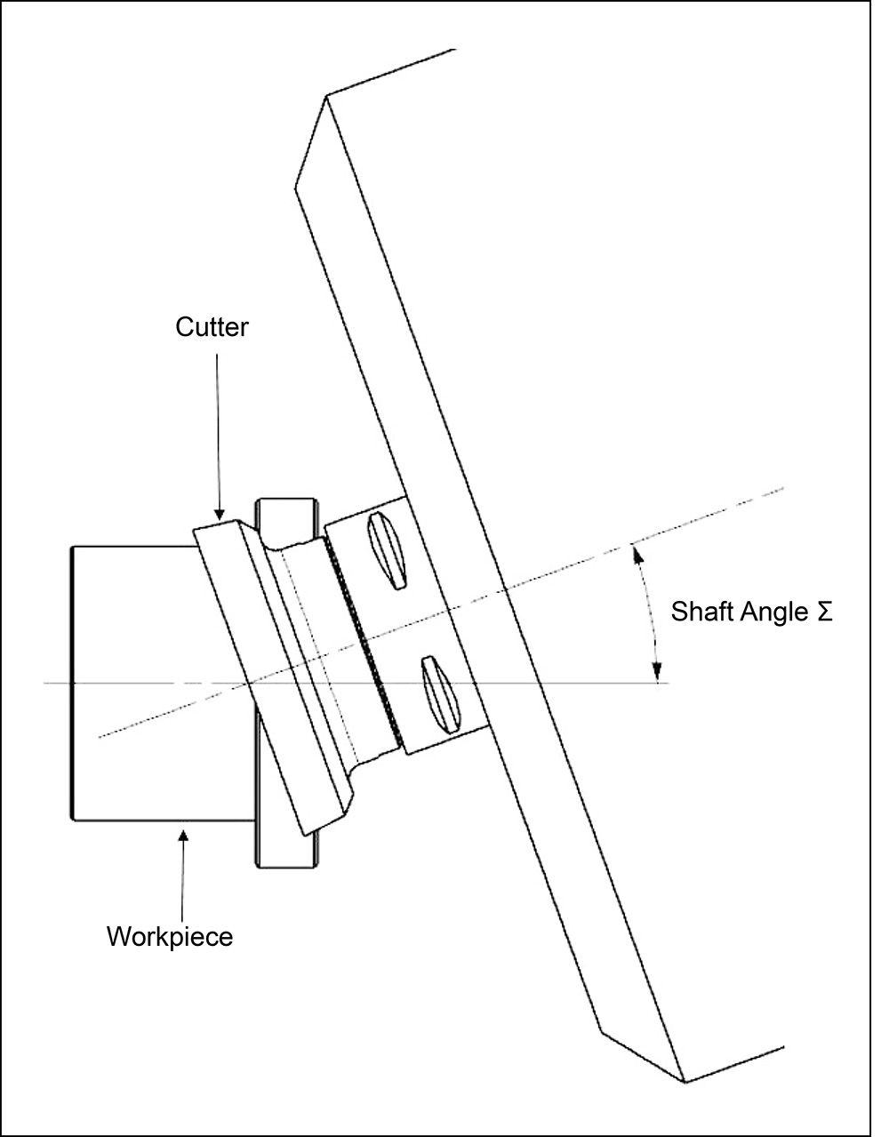
n2 = rpm of part
vc = Surface speed (m/min)
Bylund (Ref. 7) discusses that a logarithmic decay in depth of cut would be the most appropriate method to use. When assessing a logarithmic decay, it can be seen that the initial gradient of the decay is very steep, essentially taking an initial cut of extreme depth followed by many cuts of very little depth. An exponential decay would allow for a gradual transition from deep cuts to shallow cuts and is therefore more suited to a machining process. The logarithmic and exponential decrease curves are compared in Figure 2.
The AMRC previously created and tested a spreadsheet calculator that would give an exponential decrease for a given gear depth but would use maximum and minimum depths of cut to suit machining processes and also set boundaries for the exponential decay to remain within. Machining processes generally begin with deep roughing cuts to remove large volumes of material, but these are limited to a maximum depth due to the cutting force required at greater depths. The inverse applies to the final tool paths, as a minimum limit is required in order to reach the material shear force; these are the limits in which the exponential decrease must occur between in order to reach the required total gear depth. This work highlighted the requirement to further control the force through each cutting pass.
The overarching focus was to specialize in developing gear machining methods using multifunctional 5-axis machine tools in partnership and collaboration with partner companies. This was done to develop and quantify the capabilities and publicize this for the benefit of the industry and to show gear skiving as a viable option for gear manufacturers.
To achieve this, the objective was to develop and optimize a toolkit to establish capable gear skiving parameters for a range of gear and spline geometries over the course of three case studies. Previously, the AMRC developed a capability to demonstrate the gear skiving process with high performance on a few geometries, whilst supporting the development of a force prediction software model for gear skiving. The objective of more recent work was to continue and further this work into an internally developed toolkit to better understand the process, the impact of parameters, the transferability onto a range of geometries, and the limitations of the operating envelope.
The first case study’s initial focus was to undertake repeatability trials to robustly demonstrate and quantify the performance capability of the baseline process through manufacturing batches of a particular geometry (a spur gear of 4.75-inch diameter and DP 6.5, which had teeth roughed and finished in 6 minutes 20 seconds) with varying force parameters to understand the influential variables affecting this and assessing tool life. The AMRC had previously demonstrated capability for gear skiving with high productivity and to an AGMA 2015-A01 class A5 (AGMA 2000-A88 class Q12) for this baseline gear geometry, during previous parameter optimization trials. The profile, lead, and spacing inspection results are shown (measured in metric assessed against the ISO 1328-1:2013 standard) in Figure 3.

Figure 3 Extract from the metric inspection report showing achievement of (AGMA 2015-A01 class A5 (AGMA 2000-A88 class Q12).
Following this initial work, a second case study aimed to develop and test the transferability of the internally developed toolkit to predict cutting forces and establish cutting parameters for new geometries, including splines, helical gears, and comparably large ring gears. The aim was to expedite the process development and baseline performance onto different geometries. Quality, vibration, cycle time, and tool life were monitored throughout the trials.
This final case study facilitated the design of a planetary gearbox, which aimed to be representative of a number of industry sectors to allow future technology development and demonstration.
Research methodology
The first case study consisted of two initial repeatability experimental trials performed utilizing two sets of cutting parameters: experiment 1.1 with a varying force approach and experiment 1.2 with a force normalized approach, in order to qualify the preferred approach and thus validate the force modeling strategy, as well as to quantify currently achievable tool life and thus production-viability of the process.
Case study 2, a second round of trials, was performed on a newly designed artifact, which intended to incorporate a number of geometries judged most pertinent for further study. These geometries were selected to represent the automotive and aerospace industries and included helical gears and internal splines.
An extensive machining trial was undertaken to determine the feasibility to read across the previously established parameter set to alternate geometries.
Over the course of these trials, different methods for machining chatter alleviation during the gear skiving process, including spindle speed and feed rate optimization, were attempted based on dynamic data and analysis of the process.
With optimized parameters obtained for the new geometries, a tool life study was undertaken.
Case study 3, a final work stream, included the design of a planetary gearbox that would be representative of aerospace-geared turbofan applications but also suitable to showcase gear manufacturing technologies applicable to numerous industries, such as automotive and wind. To follow on from the previous work streams and transfer the findings to a larger internal geometry, a helical ring gear of this large gearbox was selected for further study of the application of gear skiving, utilizing the AMRC’s developed analysis techniques.
 Figure 4 Work breakdown structure with component models.
In parallel to the machining trials, process monitoring, and optimization work was undertaken. Moreover, a new gear skiving force software simulation was developed to predict cutting force/torque to output optimized depths of cut specific to the gear geometry. The developed simulation model differed from previous work significantly; the new model exploited a geometric repeatability assumption, which allowed for use of a single, 1D radial dexel map to record the part geometry and to predict tool workpiece engagement. This assumption greatly reduced the complexity required for simulation of gear skiving forces and was adapted for force prediction and process planning for both external and internal spur and helical gears.
In this project, different methods for chatter alleviation during the gear skiving process, including spindle speed and feed rate optimization, have been tried.
Equipment
Case study 1
A test spur gear geometry (known as the “Pulsator”) from Newcastle University’s Design Unit (Ref. 6) was utilized as the first of three workpieces for the most recent experiments. This same workpiece geometry has been adopted by the AMRC as their baseline for proof of concept on machines, tooling, and novel processes. The gear geometry and its key attributes are detailed in Figure 5, which approximate to 4.5-inch reference diameter.

Figure 5 Pulsator gear table (left) and geometry with gear skiving tool (right).
Case study 1 was completed on an Okuma MULTUS U3000, kinematically pictured in Figure 6. The OSPP300 controlled machine had a maximum turning spindle speed of 5,000 rpm, maximum milling spindle speed of 12,000 rpm, and could turn diameters up to 25.6". The AMRC machine was stocked with Hangsterfers emulsion coolant, maintained at a concentration of 8–10 percent. The gear skiving activity was always performed with the tool loaded in the ‘A Turret’ (milling spindle) of the machine, and the workpiece in the main spindle.

Figure 6 Okuma MULTUS U3000, kinematic diagram.
Inspection was undertaken using a Hexagon Leitz PMM-C, which is a precision CMM with gear inspection capability. Its accuracy specification, MPE-e, was 0.023622 + L / 800 thou, where L is the measurement length, the machine has three degrees of freedom (X, Y, Z), and it was maintained to a strict temperature range of 19.5-20.5°C.
All gear skiving tooling is specific to each gear form. The AMRC acquired their tooling for the Pulsator from Sandvik Coromant AB mounted using a Sandvik Coromant AB 392.41005C6332060 HSK 63A holder.
Case study 2
The second geometry used for the trials was a hybrid workpiece made up of three gear forms, known as Gear Shaft B (Ref. 4). The workpiece shown in Figure 7 was designed by the AMRC specifically, with the aim of expanding the range of gear geometries and gear types the AMRC had experience in gear skiving, and to assess the transferability of all previous findings to alternate geometries. The Gear Shaft B component consisted of two external helical gears and an internal spline on a cylindrical datum shaft; the key attributes of these gears and the spline are listed in Table 1. The test components were manufactured in EN36B steel with a through hardness of approximately 25 HRC.
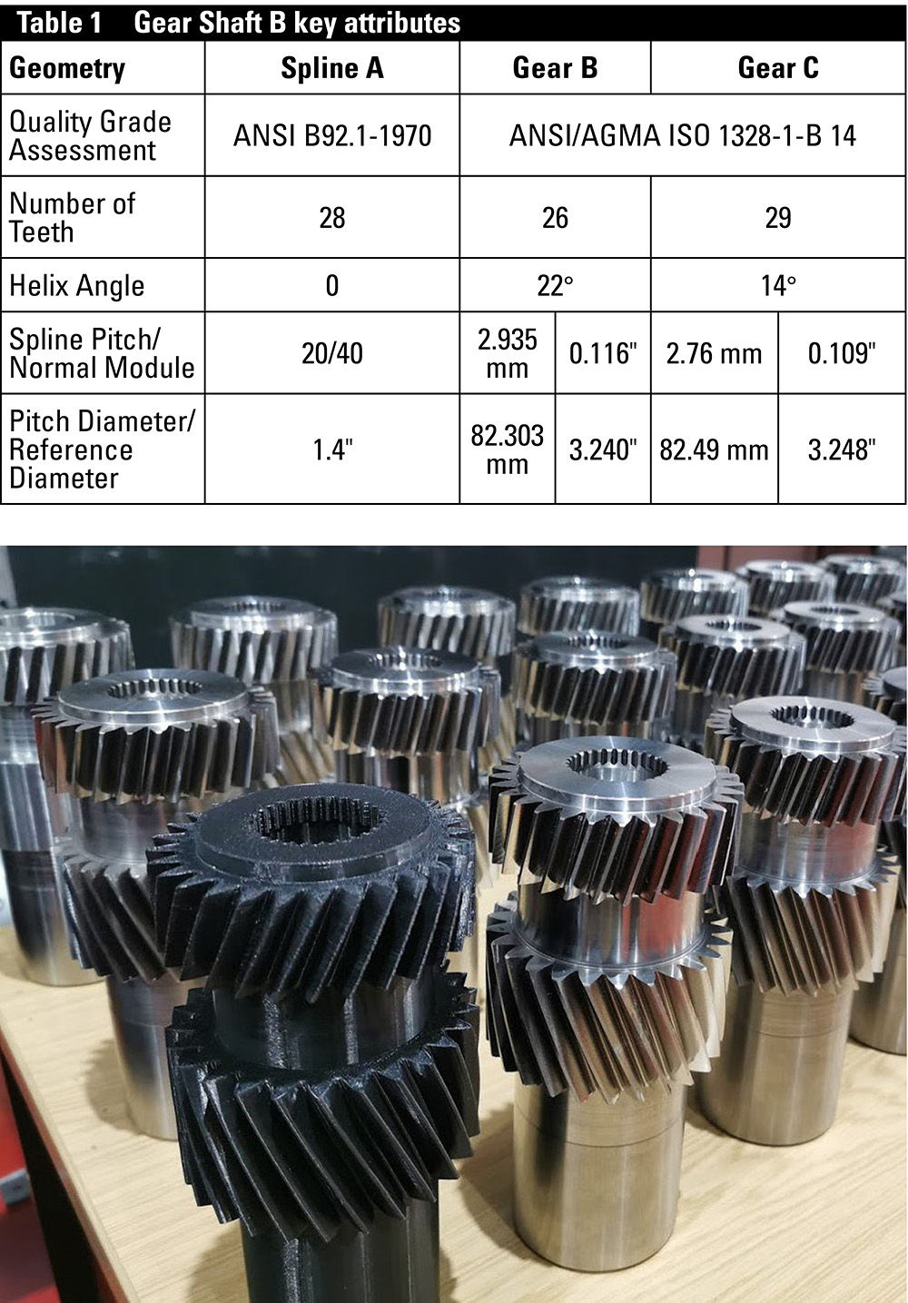
Figure 7 Gear Shaft B component geometry (Spline A internal, Gear B bottom external, Gear C top external).
Case study 2 was also completed on an Okuma MULTUS U3000 described in Case study 1 and kinematically pictured in Figure 6. The inspection was similarly undertaken on the same machine (Hexagon Leitz PMM-C) detailed and described in Case study 1.
The AMRC acquired their tooling for Gear Shaft B component from two suppliers: Horn Cutting Tools Ltd manufactured by Paul Horn GmbH and Dathan Tool & Gauge Co. Ltd. Three separate tool holders were used during the trials. For Gear C, a Sandvik Coromant AB 392.41005C6332060 HSK 63A holder was used, whilst Gear B utilized the longer length of an Erickson HSK63ASMC32100M HSK 63A holder to allow access to gear skive in the center of the shaft. Due to the small size of the cutter used to produce Spline A, a Horn Cutting Tools MLtdX60.0063.0150HSK 63A holder was used.
Case study 3

Figure 8 Aero-engine demonstrator.
The third geometry used in the most recent trials was designed internally to develop key technologies from across the AMRC Machining Group teams, demonstrated via a representation of a geared turbofan engine assembly, visualized in Figure 8. Each key component team collaboratively designed aerospace engine components that would showcase new technologies and would also be assembled into a display piece.
The gearbox design was chosen to be representative of aerospace geared turbofan applications but also be suitable to showcase gear manufacturing technologies applicable to numerous industries, such as automotive and wind.
The gearbox consisted of two helical ring gears, a double-helical sun gear, and seven double-helical planet gears with carrier. An unusually large number of planet gears was chosen in order to showcase a number of manufacturing routes (e.g., generative milling, form milling, broaching, gear skiving, hobbing, grind from solid), materials (e.g. steels, stainless, PEEK, bronze), and design attributes (e.g. varying helical gap, microgeometry, lightweighting features) in a single showcase assembly. This enables discussion of their relative merits and emphasizes the flexibility of the AMRC’s offering whilst showcasing the majority of our technologies in a single place. The components were designed with oversized wall thicknesses to maximize flexibility in the light weighting approaches planned to be showcased in future trials.
Figure 9 shows a CAD model of the full gearbox.

Figure 9 Planetary gearbox designed.
The design features large ring gears to allow demonstration of gear skiving in its element, where the productivity will offer a step change to the legacy manufacturing route, on a component type key to future 11 21FTM15 propulsion and renewables. The ring gear with its overall size and thin wall thickness is potentially the most challenging gear to produce, requiring detailed analysis and development, but with the potential for the most impact on productivity improvement.
This report includes details of the gear skiving development of the right-hand ring gear pictured in Figure 10. The key attributes of this gear are listed in Table 2. The test components were manufactured in forged BS-S132 steel in a soft condition of approximately 42 HRC (Ref. 9). This is a common aerospace nitriding steel with a tensile strength of “1320-1470 MPa” (Ref. 8). This material was recommended as industrially relevant to ring gear applications by industry experts via the British Gear Association’s Special Interest Group for Modern Manufacturing.

Figure 10 Planetary gearbox and right-hand ring gear component geometry.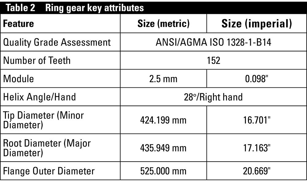
Case study 3’s ring gear trials were completed on a second machine, an Okuma MU8000V-L, kinematically pictured in Figure 11. This is a 5-axis vertical mill turn trunnion platform with gear skiving capability. The OSP-P300 controlled machine had a maximum turning spindle speed of 800 rpm, maximum milling spindle speed of 10,000 rpm, and table size of 800 mm diameter with a load capacity of 700 kg. The gear skiving activity was always performed with the tool loaded in the milling spindle of the machine, and a prepared blank fixture to the machine bed.

Figure 11 Okuma MU8000V-L, kinematic diagram.
Inspection was again undertaken using a Hexagon Leitz PMM-C detailed in described in Section 1.1.1. The ring gear utilized a Dathan Tool & Gauge Co Ltd gear skiving tool mounted on a Sandvik Coromant AB 392 41005C10040100M tool arbor with HSK100 spindle interface.
Parameter selection
Case study 1
The initial experimental trials assessed the performance of two parameter sets through the production of a number of repeats with a single tool per set of repeats. The parameter sets were trialed on a geometry the AMRC had previously gained high confidence in gear skiving, the Pulsator. Experiment 1.1 used a parameter set derived from the AMRC’s previous work considering the capability of gear skiving and its application to industry. Experiment 1.2 used a parameter set derived by the AMRC from previous work exploring the dynamics of gear skiving through modeling and simulation to provide a tool to further assess the process.
Case study 2
The subsequent experimental trials in case study 2 aimed to transfer all the accumulated prior knowledge from the previous work at the AMRC to alternative gear geometries to broaden gear skiving knowledge and provide a greater understanding of how the gear skiving process performs for geometries that are likely to be applicable to the wider gear industry. This included a single test piece with two different external helical gears and an internal spline. The first 26 test pieces were produced in an iterative manner, with CMM inspection and data analysis between each test piece to reflect on performance and make the relevant parameter changes to improve the quality and understanding of the subsequent gears.
A following 19 test pieces were produced over a five-day period, without any changes to parameters, to further assess the limit of tool wear.
Case study 3
A similar iterative approach was utilized during Experiment 3.2, trials on the Ring Gear geometry. Parameters were selected based on the performance of the two previous case studies but limited to produce static cutting forces ranging from 500 N–1,000 N. Figure 12 plots the trialed tool spindle speeds along the graph produced from the dynamic tap testing process that was performed at the start of machining. A speed that intersects the graph at an area of high magnitude would have undesirable performance, as the machining frequency would match the natural frequency of the tool assembly or workpiece setup.
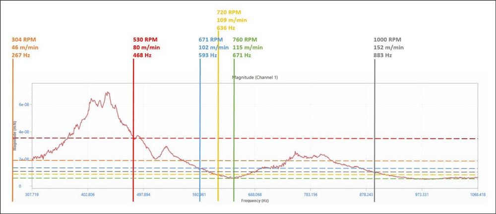
Figure 12 Tool spindle speed—frequency magnitude analysis.
A new gear skiving force simulation capability was developed to predict cutting force and torque during gear skiving operations. The new model exploited a geometric repeatability assumption, which allowed for use of a single, 1D radial dexel map to record the part geometry and to predict tool-workpiece engagement. This assumption greatly reduced the complexity required for the simulation of gear skiving forces and was adapted for force prediction and process planning for external spur and helical gears.
The force prediction model was implemented during the Gear Shaft B and Ring Gear experimental trials to provide a series of depths of cut for both external helical gears, which was specifically designed to control the forces at the specific depth for each pass specific to the individual gear geometry.
Load data recorded from the machine during the cutting process was used for comparison against the theoretical forces predicted by the model to refine the output and improve the accuracy of the depths of cut to reduce the level of vibration and improve the quality of gear produced.
Results and observations
Case study 1
During Experiment 1.1, with varying force parameters, all components conformed repeatedly to an AGMA 2015-A01 Class A7 (AGMA 2000-A88 class Q10), whereas Experiment 1.2, with force normalized parameters, only conformed to Class A7 on 45 percent of the components tested. The remaining components were a range of Class A8–Class A11 at worst, despite consistent cutting parameters. The range of performance in Experiment 1.2 was not accredited to tool quality, due to the lack of consistent errors within the inspection report. Due to the pattern of results not showing a constant degradation in quality as part number increased, the range of results was also not attributed to tool wear.
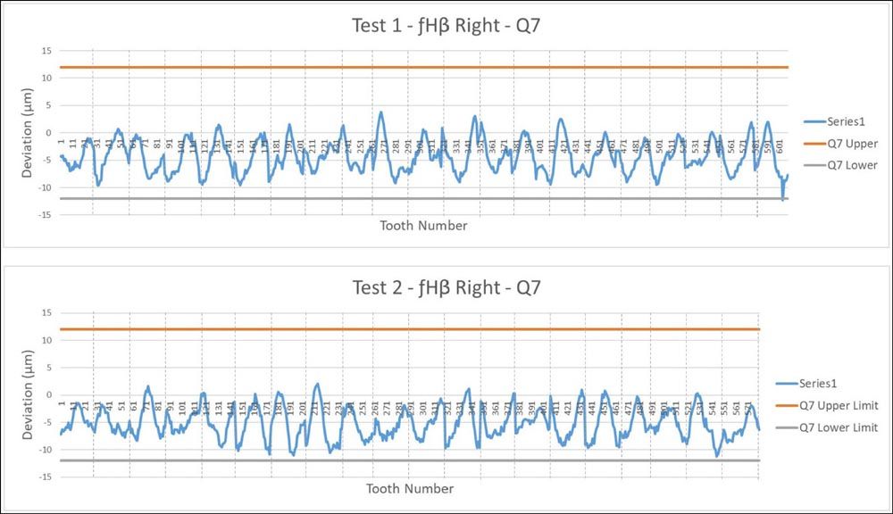
Figure 13 Experiment 1.1 (top) and 2 (bottom) fHβ Right profile results.
To further analyze any pattern in the results from component to component, the inspected profile and lead features of each tooth across the batch were plotted sequentially for all profile and lead features for both Experiment 1.1 and 1.2. Figure 13 shows the metric plots of the right flank line angle error (fHβ) profile results for both experiments. As the gear skiving cutting process contacts several teeth at any one time, the first tooth cannot be accurately determined. For the purpose of the below graphs, a tooth was selected at random with all further teeth counted in a clockwise direction (viewed from the datum B end).
The metric plots in Figure 13 show a pattern representative of the majority of the profile and lead inspection results. When plotted in sequence the teeth showed an emerging wave pattern with some—but little—noise. This pattern appeared to be consistent throughout the full experimental batches indicating a potential behavioral pattern within the machine tool that was not affected by a component change or machine restart—the components within the batch are separated by hashed vertical lines in Figure 13.
Figure 14 shows the best quality gear out of the two batches of components. Experiment 1.1, Component 19 conformed to an AGMA 2015-A01 class A6 (AGMA 2000-A88 class Q12).
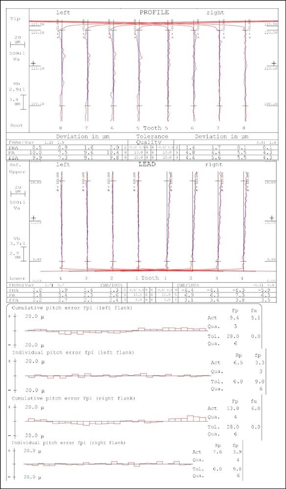
Figure 14 Extract of inspection data for Experiment 1.1, Component 19.
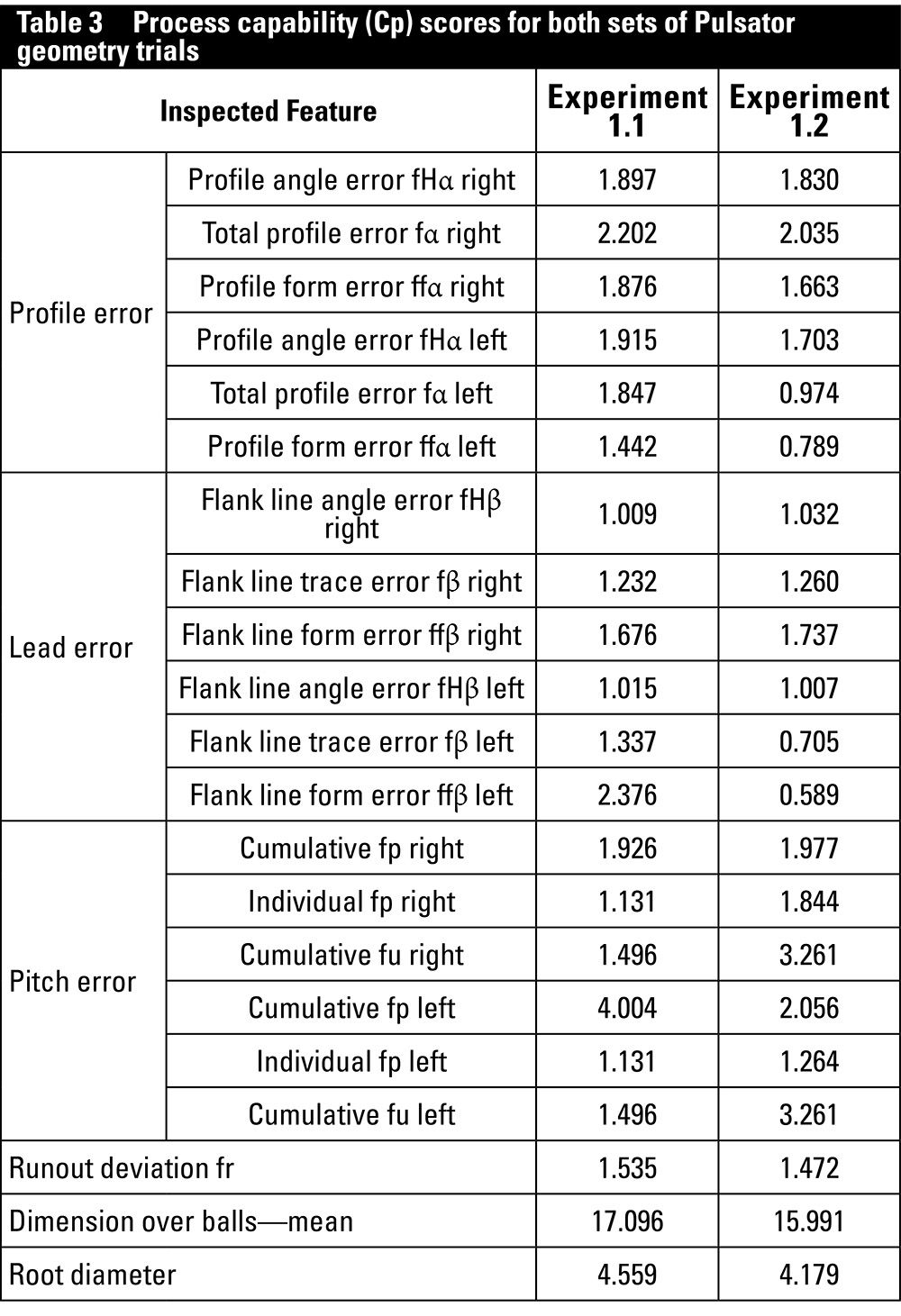
Table 3 shows the Cp data, which assesses the repeatability of the results through the amount of scatter alone, regardless of any skew in the data. The Cp, rather than the Cpk (with skew), was chosen for the process capability assessment due to intentional offsets that were made for the trial. For example, to improve the quality of the tooth profile, the root diameter was intentionally offset towards the top tolerance. Therefore, despite highly repeatable results, the process capability score for root diameter was low at 0.359 (1 σ) due to the off-centered results. When the skew is removed from the equation, the root diameter shows a favorable process capability score of 4.559 (6 σ), as seen in Table 3.
Tool life
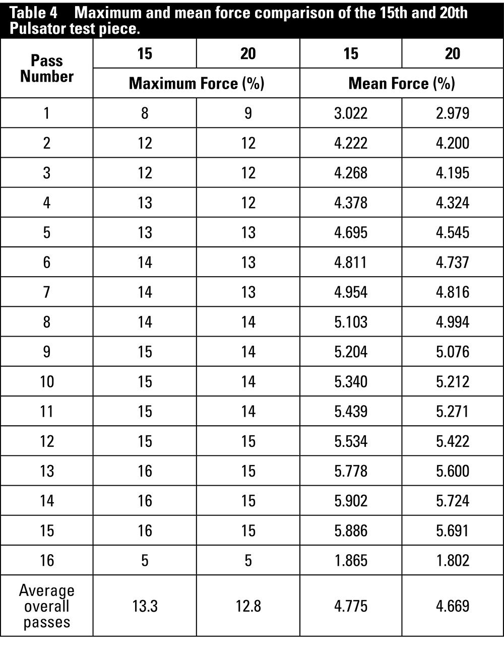
The life of the tooling used during both sets of parameter trials on the Pulsator geometry was monitored and assessed under a microscope every fifth gear. The trials saw 21 components produced using the varied force parameters in Experiment 1.1 and 20 components produced using the force normalized parameters in 1.2. This result is comparable to and supports the AMRC’s previously published tool life of 22 gears for the same gear geometry (Ref. 5). Due to increasing wear levels throughout the trial, the teeth chipped at some point after the tool was inspected on the microscope after production of the fifteenth test piece. However, there is no data to suggest at which point before the final microscope inspection at 21 and 20 test pieces the teeth became chipped. Up to the point of tool fracture, no consequence of tool wear was reflected in the gear metrology reports. Table 4 compares the milling spindle load data recorded from the machine for the fifteenth and twentieth test pieces produced in Experiment 1.2, as no data was recorded during the production of test pieces 16–19. The table compares the maximum and average loads on a pass-by-pass and overall basis. This shows that no increase in load was recorded after the tool became chipped. In the majority of cases, the earlier test piece showed a reduced load compared to the latter.
Case study 2
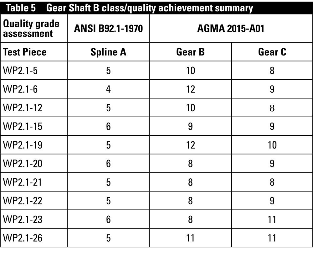
With regards to case study 2, trials focusing on the two helical gear forms and the internal spline of Gear Shaft B; Table 5 summarizes the class of gear achieved by both gears and the spline on all ten test pieces inspected using the Hexagon Leitz PMM-C from the 26 parameter optimization test pieces. Spline A could be seen to repeatedly achieve at least a Class 6 ANSI B92.1-1970 standard with a desirable Class 4 achieved on an early test piece. Gears B and C were both assessed against the AGMA 2015-A01 standard, with Gear B repeatedly conforming to a Class A12 standard, but at best, achieving a Class A8 on 40 percent of the test pieces. Gear C conformed to an improved Class A11 standard but only achieved a Class A8 on 30 percent of the inspected batch. The large range of results was anticipated due to the high number of parameter changes within the first 26 test pieces for both Gear B and C, creating the inconsistency.
When evaluating the profile (PVar) and lead (LVar) data of the ten splines inspected on the Hexagon Leitz PMM-C, seven full splines conformed to a Class 5 standard when assessed against ANSI B92.1 standard, with one of these conforming to a Class 4. Breaking the splines into individual flanks, 99.375 percent flanks conformed to a Class 5 with respect to profile (PVar) and 98.889 percent a class 5 with respect to lead (LVar). When assessed against a Class 4 95.625 percent flanks conformed to a Class 4 PVar and 78.75 percent a class 4 LVar. These results show a high level of repeatability which enhanced the confidence of the gear skiving process to produce splines with excellent productivity. The program run for Spline A took 1 minute 36 seconds in total including tool change, with only 58 seconds in cut, to repeatedly gear skive to the above standards. Figure 15 shows the profile section of the inspection report of an example spline conforming to a Class 4.
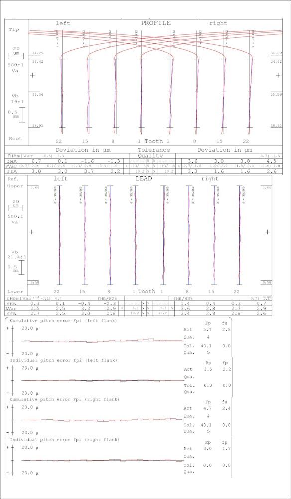
Figure 15 Extract of the inspection report for WP2.1-6.
The objective of the project for dynamic analysis was to develop a simulation toolkit to simulate gear skiving mechanistic process requirements and to provide insight for feasible parameter selection for a range of gear and spline geometries. The AMRC applied process monitoring, optimization, and the development of a cutting depth optimization software for gear skiving, through consideration of the process optimization aspects of this project through practical data capture, analysis, processing, and interpretation of data. This data included audio recording during the cutting process, the endured spindle forces, and the static impact testing results.
Tool life
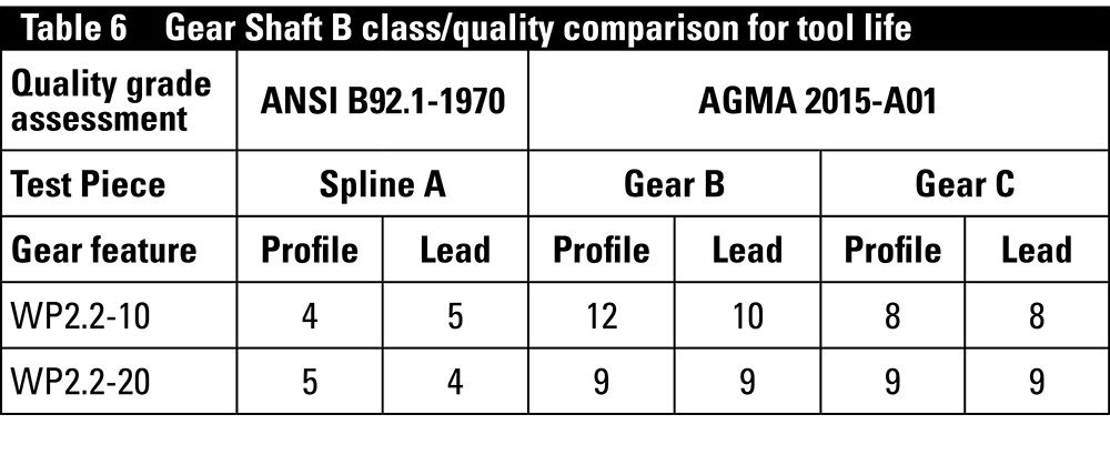
After the iterative parameter development of Gear Shaft B trials, a short tool life assessment with consistent parameters was performed. Of the nineteen additional test pieces produced in the tool life trial, only two were evaluated by the Hexagon Leitz PMM-C, due to budget and time constraints. The mid-batch test piece—WP2.2-10—and the final test piece—WP2.2-20—were selected to give the best overview of overall batch performance. Table 6 summarizes the performance of these two test pieces.
Based on the two inspected test pieces, the repeatability of the process was in question. As the tool began to wear throughout the trial, it was anticipated that the performance would decrease as the trial progressed. As Table 6 shows, the quality of Gear B was improved on the final test piece when compared to the mid-batch test piece; the assumption from this is that there was a lack of consistency between all nineteen tool life test pieces, which were produced as direct repeats, without any parameter alterations.
Images of the tool were taken prior to and on completion of the trials. Comparison of these images showed the tools used to produce the two external helical gears appear to have worn, however, the visible wear was minimal. The tool used to produce the internal spline had no visible signs of wear under the microscope. The tool wear progression of the three gear skiving tools used for Gear Shaft B has been compared before the trials, after 26 gears/splines and after 46 on completion of the experimental trials—Spline A in Figure 16, Figure 17, Figure 18, Gear B in Figure 19, Figure 20, Figure 21 and Gear C in Figure 22, Figure 23, Figure 24.
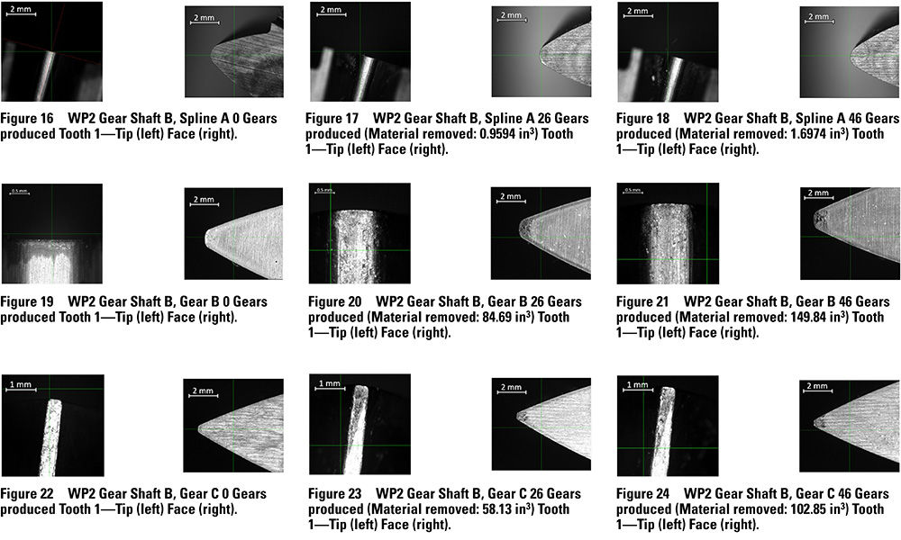
Analysis of the tool images along with the gear inspection reports implies that all three tools could continue to skive gears to the same standard as was achieved during the tool life trial. The tools had therefore shown the manufacturability of at least 46 components, removing 149.84 in3 of material between re-grinds, despite the varied parameters (some of which were sub-optimal) used during this trial.
Case study 3
In the initial stages of Experiment 3.2 trials gear skiving the right-hand ring gear, the methodology and setup to use were defined as illustrated in Figure 25.
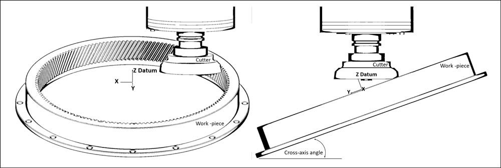
Figure 25 Proven gear skiving strategy in the XZ (left) and YZ (right) planes.
Six gears were produced to full depth, trialing depths of cut and parameters generated by the mechanistic force model to a force limitations of 1,000 N on the first gear produced and 500 N on the final gear. Between these gears, a range of parameters (spindle speeds, feed rates, depth of cut) and methods, including spring passes and multiples of finishing cuts, were tried to improve an inconsistent/wavy surface texture that was produced on the flanks when gear skiving. The surface texture was improved through these trials but was not eliminated. The final surface and an extract of the lead inspection report are shown in Figure 26.
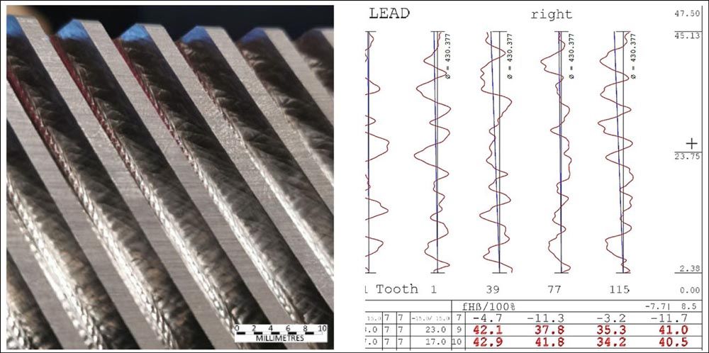
Figure 26 Final surface finish (left) and extract of lead inspection (right).
The final Ring Gear produced achieved a Class 10 ANSI B92.1-1970 for profile, 11 for lead, and cumulative pitch with a runout of Class 9. Analysis of the lead shows that the slope deviation is conforming to the targeted Class 7. The form deviation values, however, were more representative of a class 10 gear in the majority of cases but achieved a Class 11 overall. A deeper analysis of the profile results showed more consistency with the majority of results, equating to Class 10.
Tool life
Throughout the duration of the ring gear trials, a range of parameters was trialed in an attempt to refine the cutting process. Some of these were sub-optimal, hence the gear skiving tool was observed to be worn after the production of six test pieces. Figure 27 and Figure 28 compare a tooth of the gear skiving tool before use and after the six test pieces.
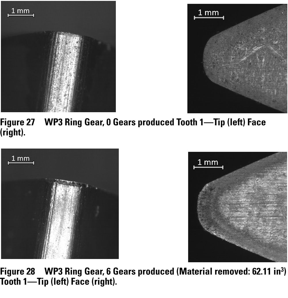
Due to the size of the ring gear compared to the Pulsator and Gear Shaft B, the tool life was not anticipated to meet the same number of gears per tool, as the material removal per gear was substantially increased. The ring gear has over five times the number of teeth of the other three gears discussed. When the volume removed was compared, the ring gear results exceed the life of the Pulsator, 62.11 in3 to 40.45 in3 (912 teeth to 609) respectively. But the tool did not achieve the same results as the two used to produce the gears in Gear Shaft B, where 149.84 in3 and 102.85 in3 were removed (1,196 and 1,334 teeth) with minimal wear observed.
However, the tool life of the Ring Gear was expected to improve under optimized production parameters.
Conclusion
AMRC is specializing in developing gear machining methods using multifunctional 5-axis machine tools in partnership and collaboration with partner companies. This project has demonstrated a viable machining method, applicable to multifunctional machine tools, in gear skiving. This modern gear-cutting process is gradually being adopted by industry, but its application to date has been considered a secretive black art. The focus is to develop and quantify the capabilities and publicize this for the benefit of the industry.
In machining batches of the initial Pulsator test geometry during Experiment 1.1, with varying force parameters, all components conformed repeatedly to an AGMA 2015-A01 Class A7 (AGMA 2000-A88 class Q10).
Experiment 1.2 complemented previous tool life assessments on the same geometry completed at the AMRC by achieving a tool life of 20 and 21 gears.
Further test geometries were trialed, including helical gears and internal splines. An AMRC software model was developed to predict cutting forces and establish cutting parameters for new geometries in order to expedite the process development. A range of cutting parameter strategies was employed to establish an optimal approach for enhanced quality and reduced vibration. Cutting tool life was established as in excess of 45 components for this range of geometries.
The final work stream discussed successfully developed skills to devise a design of a planetary gearbox representative of a number of industry sectors, which will allow for future technology development and demonstration, which can be directly relevant to a number of industries. Process capability and an understanding of how to rough ring gears via the novel gear skiving method on a multifunctional machine tool were achieved through the development of previous experience and refinement of the mechanistic force model to assist in parameter selection.
This development and validation allowed the achievement of a Class 11 ANSI B92.1-1970 gear in approximately 35 minutes, including a final spring pass. Some earlier gears were produced in less than 20 minutes but to reduced quality. A closer look at tool design for performance improved the understanding of how the mechanics of tool design affects capability, highlighting an area of opportunity for future research and collaboration with tooling suppliers. Further to this, the project built on previously established stakeholder relationships through collaborative investigation, feedback, and discussion at the design, manufacture, and analysis stages of the project, which proved great value in the AMRC’s wide network of internal teams and external partners.
Gear skiving offers great opportunities for production with step-changing productivity, particularly for internal gears, whilst offering high-quality finishing capabilities and being applicable on a 5-axis machine tool with its inherent flexibility and multifunctionality. The development and application of the toolkit proved beneficial and showed to be applicable to a range of gears with great potential for time saving.
Future vision
Through this project, AMRC has gained an understanding of how to translate the excellent performance obtained for a baseline gear geometry to a range of further geometries, yet there remains a great deal to learn about the process in order to develop its performance. Areas of opportunity include:
- Further development of the mechanistic force model would be advantageous. A design of experiments (DOE) approach would allow for a number of variables to be investigated and subsequently, feed into the model to improve performance and understanding.
- A continued investigation with the aim of removing the inconsistencies in the surface of the flanks would prove beneficial to all future gear skiving work on the Okuma MU8000V-L.
- From a dynamics point of view, an enhancement would be anticipated by using an artificial intelligence (AI) method. For example, the vibration could be monitored, and process parameters were then optimized during the machining process through reinforcement learning methods.
The planetary gearbox assembly is now designed, and so the planet gears, planet carrier, and sun gear, as well as the ring gears, are now available as baseline geometries, without IP restriction, to develop and showcase numerous manufacturing technologies.
AMRC and our partners are actively pursuing routes to furthering the research on gear skiving in these areas and would welcome engagement from AGMA members and others in opportunities to collaborate.
Acknowledgements
The authors would like to thank the High-Value Manufacturing Catapult and Innovate UK for funding the research detailed in this paper to allow the AMRC to develop and understand the capability of the gear skiving process.
Thanks to the three tooling suppliers; Dathan Tool & Gauge Co. Ltd., Horn Cutting Tools Ltd. and Sandvik Coromant AB for their continued development, interest, and support in the area. The machine supplier NCMT has assisted with data collection, analysis, and development through much of the AMRC’s gear skiving development work on the OKUMA platforms for years, which reaches beyond the remit of this paper.
Also, thanks to Dontyne Systems Ltd. for providing software, training, and support to allow the design and analysis of the range of gear profiles that have been used throughout this paper.
And a final thank you to the British Gear Association’s Special Interest Group for Modern Manufacturing for continued support and for providing a range of expertise and many years of collective experience that provided vital recommendations and advice in the design stages, with a special mention to the Newcastle University Design Unit for allowing the AMRC to adopt one of its gear profiles and for their continued support.
Printed with permission of the copyright holder, the American Gear Manufacturers Association, 1001 N. Fairfax Street, 5th Floor, Alexandria, Virginia 22314. Statements presented in this paper are those of the authors and may not represent the position or opinion of the American Gear Manufacturers Association.
References
- Klocke, F. and Brecher, C., and Löpenhaus, C., and Ganser, P., and Staudt, J. and Krömer, M., 2016, “Technological and simulative analysis of power skiving,” Fraunhofer Institute for Production Technology, Laboratory for Machine Tools and Production Engineering, Aachen, Germany.
- Weppelmann, D. E., 2014, “MMS Online,” from www.mmsonline.com/articles/a-breakthrough-in-power-skiving. [Accessed 06 January 2018].
- McClarence, E., 2017, “Power skiving for Greater Productivity,” Metalworking World, Sandvik Coromant, from www.sandvik.coromant.com/en-gb/mww/pages/t_powerskiving.aspx [Accessed 06 January 2018].
- Cousins, B., 2019, “AI4125A-AMRC-DR-190913A-02.”
- Cook, B., 2019, “What is power skiving?,” A step change in Gear Manufacturing, The University of Sheffield Advanced Manufacturing and Research Centre, Catcliffe, pp.11.
- 2015, “P5699-39-29-01-00 Rev 2,” Gear Technology Centre—Design Unit.
- Bylund, N., 2017, “Understanding the basic principles of power skiving,” Gear Solutions, from www.gearsolutions.com/article/detail/6782/understanding-the-basic-principles-of-powerskiving. 6.Research. [Accessed 23 March 2018.]
- Smiths Marketing Team. n.d. “S132 Steel Bar. Smiths Metal Centres Limited 2020,” from www.smithmetal.com/s132.htm [Accessed 16 February 2021].
- Haihong International Trade. 2011. “S132,” from www.ccsteels.com/Structural_steel/6.html [Accessed 29 April 2021].


