•Within each profile and generating grinding finishing process there are continuous and discontinuous distinctions (see Figure 2).
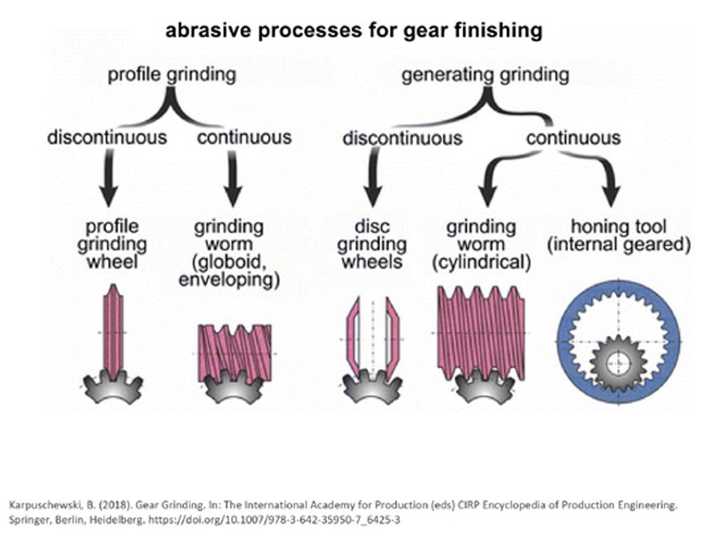
Figure 2
•Continuous processes refer to the gear and grinding wheel staying in rotation as the tooth profile is formed.
•Whereas, discontinuous means the grinding wheel retracts from the grinding wheel after each gear tooth is formed.
Continuous generating grinding is a unique and extremely demanding grinding process. Profile deviations and surface finish must be kept to an absolute minimum because of gear noise challenges. However, when considering the involute profile of the gear, the arc length and the chip thickness generated from the grinding cycle vary dramatically from the tip to the root. So, one edge will wear faster than the other, creating some difficulties when trying to increase the grinding wheel life. If these grinding wheels fail, it will typically be either due to profile deviation, from grinding burn, or as a result of waviness that is generated on the gear flank.
For grinding processes, it is also important to pay attention to chip length and chip thickness. For example, cylindrical OD grinding processes typically have a small contact area and will generate a chip with a large chip thickness, but short chip length. Creepfeed grinding, however, has a small chip thickness and a long chip length.
The chip thickness is generally a good index of how aggressive a grinding cycle is. The larger the chip thickness value, the more aggressive the grinding operation. Chip length, on the other hand, has a big effect on grinding temperatures, and chips with a long chip length are at risk of becoming embedded in the grinding wheel. With longer chip lengths, higher amounts of grinding wheel porosity are necessary to all the chips to be properly evacuated from the grinding wheel.
With surface grinding and profile gear grinding, the chip length is typically between three and four millimeters. However, continuous generating gear grinding has extremely long chips compared to these processes, making it closer to a creepfeed grinding process. A high porosity wheel is required to accommodate long chips. And a strong wheel is needed because the chip thickness is also fairly high (see Figure 3).
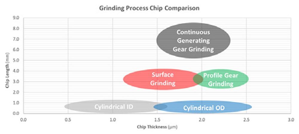
Figure 3
Grinding Wheel Wear Mechanisms
Both the abrasive and the bond are grinding wheel wear mechanisms. Figure 4 shows three abrasives with bond posts connecting them. The first type of abrasive wear is chemical or may have resulted from the flattening or flat spotting of the abrasive grain. When there are very flat abrasive grains, metal capping or loading will adhere to the tips of the grains, which can generate heat. Next is micro-fracturing, which is the preferred wear mode for abrasives. Micro-fracturing generates very small cracks that keep the grinding wheel sharp. The third type of abrasive wear is macro fracturing where the grain actually fractures in half. This accelerates wheel wear, increasing the overall surface finish.
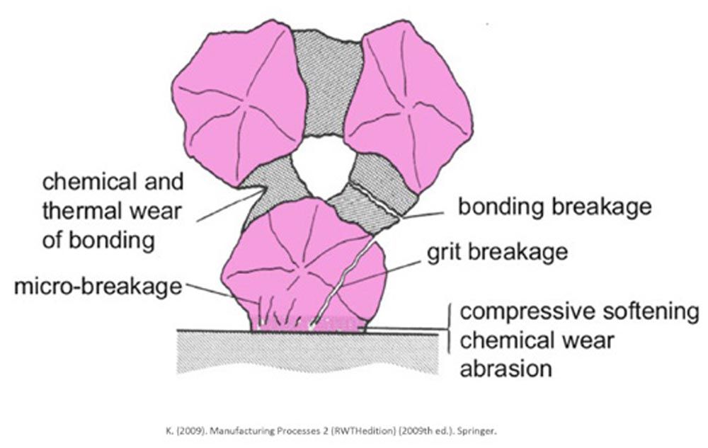
Figure 4
There are also three different primary types of bond wear. First, abrasive pullout is when the abrasive is totally pulled from the bond. In the instance of fracture bond wear, the bond will break. Or there is chemical or thermal wear that occurs from high grinding temperatures.
Essentially, you can enhance grinding wheel performance by either improving the wear resistance or toughness of the grain, or by increasing the strength and wear resistance of the bond. Wheel wear is also impacted by the homogeneity or uniformity of the grain dispersed throughout the grinding wheel. Even distribution of the grinding forces will create even wear, which is important for reducing transmission error and tooth variation.
When quantifying grinding wheel wear, G-ratio is an important index. G-ratio is defined as the ratio between the volume ground from the workpiece and the volume lost from the grinding wheel. So, a higher G-ratio indicates that a grinding wheel can remove more material before it requires dressing to restore the profile. G-ratio becomes even more critical as the grinding wheel gets smaller and reaches the end of its life because wheel wear increases as wheel diameter decreases, Also, the wheel speed is reduced as the wheel gets smaller, but because wear increases from the smaller wheel diameter, wheel volume is decreased.
Figure 5 shows the typical wear that you would see in continuous generating gear grinding. The profile and flank would start to become wavy, resulting in slope errors and form errors.
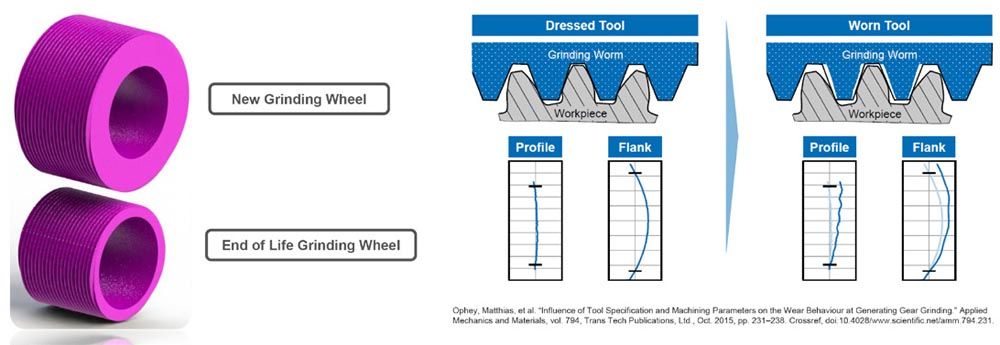
Figure 5
Monitoring the G-ratio is important for continuous generating gear grinding because these wheels should be running at a constant RPM for the best results. Performance must be maintained from the new grinding wheel diameter to stub.
The G-ratio is also directly affected by how aggressive the grinding cycle is. Chip thickness is a good indicator of aggressiveness. Different factors will affect the aggressiveness of the grinding cycle to varying degrees, some more than others. Factors include wheel speed, the number of wheel starts, feedrate, wheel diameter, and depth-of-cut.
Aggressive grinding cycles typically require tougher abrasives and stronger bonds to maintain wheel form, creating a challenge when trying to keep grinding temperatures low. It is critical to avoid excessive heat generation in gear grinding, as high temperatures can lead to thermal damage of the gear flank. Subsequently, thermal damage can cause tensile residual stress, which will significantly reduce the load-carrying capacity and fatigue life of the gear tooth. To help reduce grinding temperatures, grinding parameters can be adjusted, but these adjustments are usually at the expense of cycle time and overall productivity. Thankfully, new grain and bond technology advancements can reduce grinding temperatures while maintaining productivity.
Abrasive Types, Evolution
There are two commonly used abrasive types in gear grinding—fused and sintered. Fused abrasives tend to break apart into large particles, while sintered abrasives are designed to break down slowly into smaller particles while maintaining sharpness. Superabrasives are also an excellent option, although their usage is still emerging in gear-grinding applications (see Figure 6).

Figure 6
Abrasive grain comes in several forms. Aluminum oxide is one example that will change in appearance, toughness, and hardness based on the manufacturing process. Brown or natural aluminum oxide is typically brown and has a high toughness but lower hardness due to its impurities. White or pure aluminum oxide is typically white and is very sharp and reliable. By adding chromium oxide or titanium oxide, the properties of the abrasive can be modified. Adding ~0.2 percent chromium oxide results in pink aluminum oxide, and adding ~2 percent chromium oxide creates red/ ruby aluminum oxide. In gear grinding applications, pink and red aluminum oxides are the most used (see Figure 7).
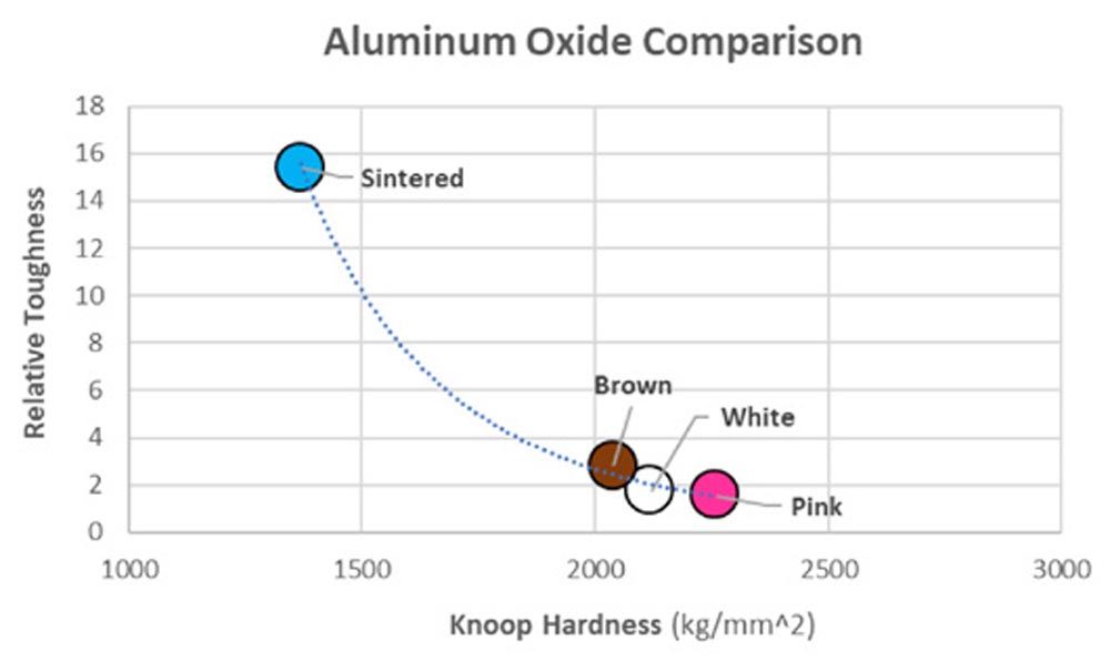
Figure 7
Seeded-gel ceramic abrasives are another form. Norton revolutionized the grinding industry in 1986 when it introduced “SG”, the first of its kind, and Norton has been continually enhancing this seeded-gel ceramic technology ever since. SG is a small microstructure that creates a very tough abrasive, enabling controlled grain breakdown at high material removal rates. Seeded-gel abrasives typically have ~1:1 aspect ratio and provide a good balance of performance and quality. Norton Quantum, also known as NQ, was released in 2007 adding fracture point inducers to increase grain friability, resulting in reduced grinding forces when compared to its SG predecessor.
In 2021, Norton introduced its newest seeded-gel ceramic abrasive, Quantum Prime also known as NQN. Norton Quantum Prime has a smaller grain size, reducing wheel wear and producing finer surface finishes. This newest seeded-gel abrasive technology is well suited for gear grinding due to its ability to maintain sharpness while consistently breaking down (see Figure 8).
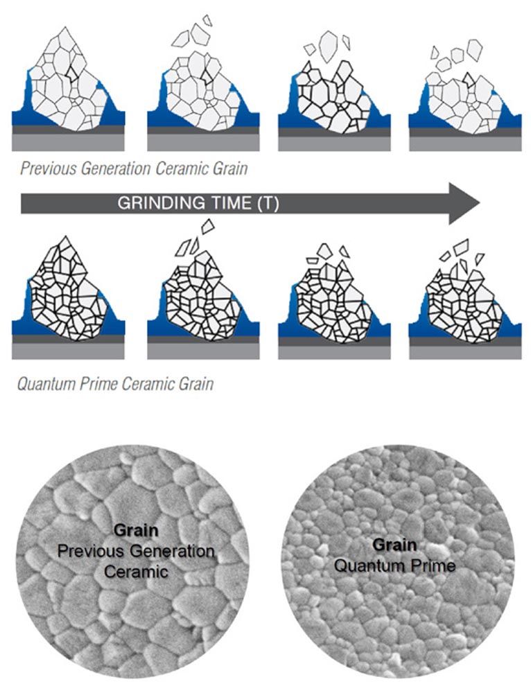
Figure 8
Norton released the first extruded seeded-gel abrasives in 1999 called “TG”. Due to its geometry, extruded ceramics facilitate higher material removal rates and higher G-ratios than traditional seeded-gel ceramics. Typically, extruded ceramic abrasives are used in larger, cylindrical gears that require high material removal rates, or for grinding gears from solid. Norton “TQ” is the second-generation TG grain that uses NQ chemistry to produce smaller fracture plans. The smaller microstructure results in longer wheel life and lower grinding power.
It is important to note that in gear grinding, ceramic wheels are not typically 100 percent ceramic, instead they are blended with various aluminum oxides to make the grinding wheels more economical. In continuous generating gear grinding, ceramic concentration is typically in the range of 10–50 percent with 10–30 percent being the most common. The concentration of ceramic and the selection of the secondary abrasive play a big role in the grinding wheel performance. Higher ceramic grain content improves profile retention and extends grinding wheel life at the expense of increased dresser wear.
Bonds
The purpose of a grinding wheel’s bond is multifaceted. Bonds enable the abrasive to retain sharpness and enough porosity for coolant and grinding chips. They also release worn abrasive, and reduce bond and workpiece interaction as much as possible. Typically gear grinding wheels tend to use a porous structure and relatively soft bonds to keep grinding temperatures low. The disadvantage is this also increases wheel wear.
A new bond technology from Norton for gear grinding reduces grinding temperatures and forces. The novel bond technology allows the bond itself to grind and remove workpiece material rather than rub against the workpiece, generating heat. An abrasive phase is grown into the bond during the manufacturing process which enhances grinding wheel performance (see Figure 9).
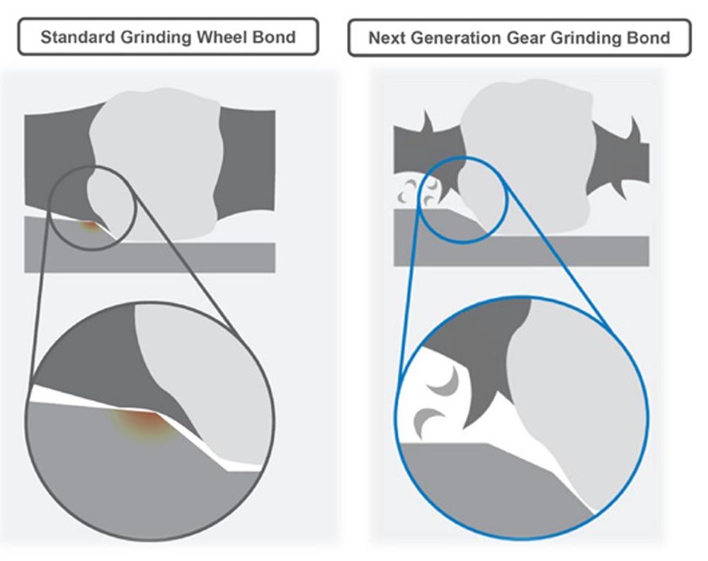
Figure 9
New Grinding Wheel Technologies
As gear designs are influenced by EV and other industries that demand lower, finer finishes, grinding wheels alone are unable to achieve the surface requirements. By using a dual polishing grinding wheel, the roughing and finishing process is performed with the grinding portion of the wheel, while an additional polishing step is performed with the wheel’s polishing portion. The resulting polishing creates a much lower surface finish than previously attainable with just a grinding capability. And significantly lower flank roughness values result in reduced micro-pitting of the gear flank as well as improved transmission efficiency (see Figure 10).
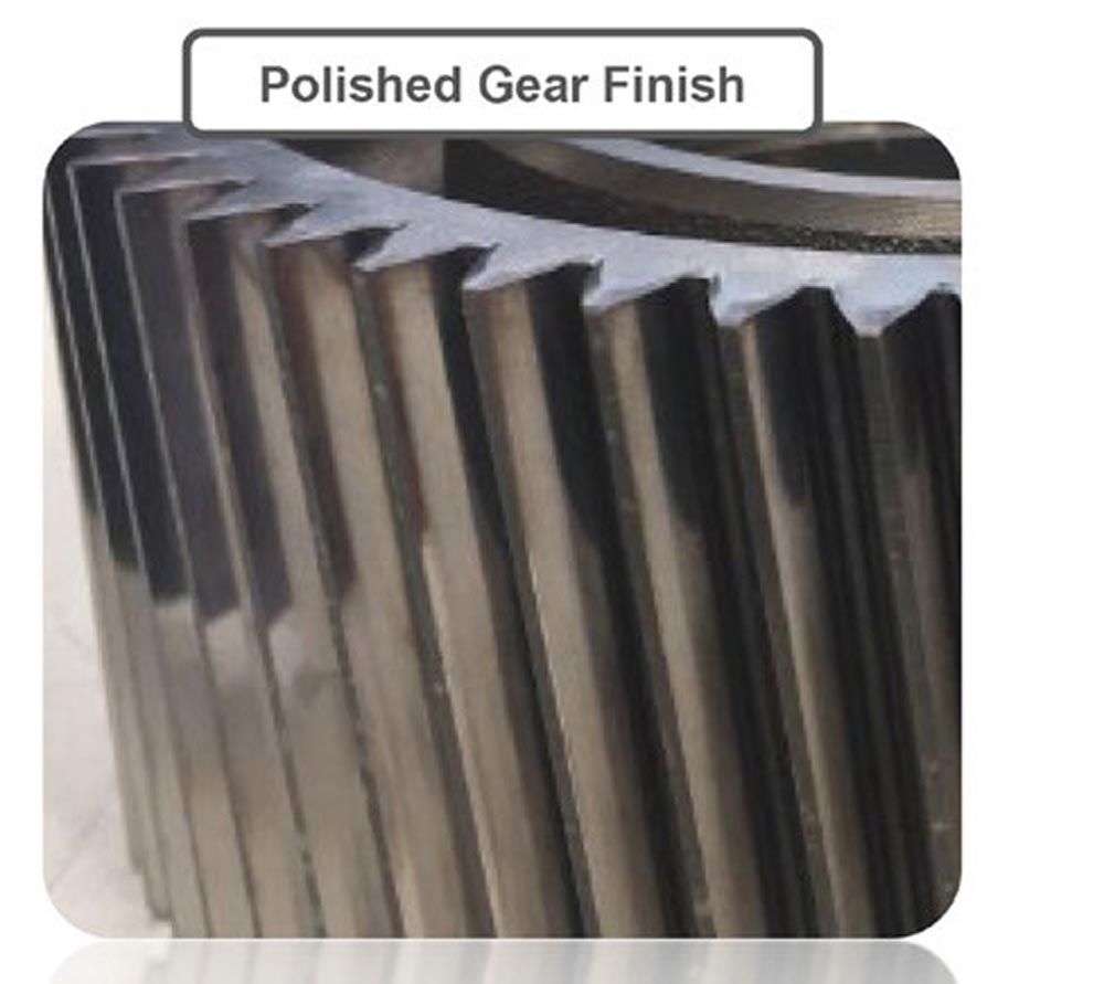
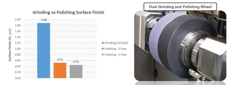
Figure 10
Also, the use of a hard resin instead of a typical rubber bond reduces the amount of polishing wheel deformation during the polishing cycle and improves the form accuracy of the gear tooth.
Benefits Proven in Tests
Field testing has shown that the newest generation gear grinding wheel bond system provides a lower specific power at all material removal rates, indicating that the abrasive phase grown into the bond is reducing friction between the bond and workpiece. Grinding wheel wear is also lower, likely due to the reduction in grinding forces and temperature (see Figure 11).
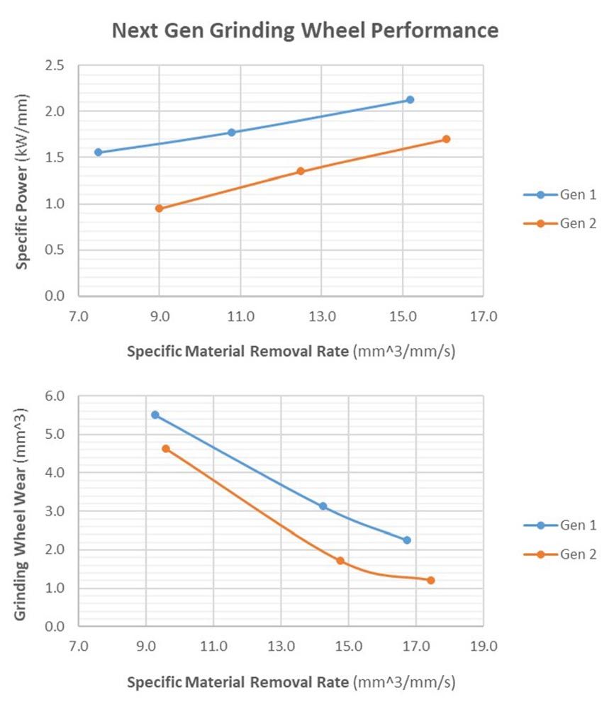
Figure 11
The profile retention was also improved with the new bond technology. When comparing the generation 1 wheels with the generation 2 gear grinding wheels, Ffα was reduced ~25 percent on average. This improvement results in lower process Cpk, and makes it possible to extend the dressing interval of the wheel.
nortonabrasives.com
