Differential gear manufacturers began moving away from the tried-and-true Revacycle broaching process to forgings some 30 years ago. At the time, forged differential gears seemed almost tailor-made to meet the needs of automotive, truck, and other vehicle producers: Relatively inexpensive when produced in high volumes; able to deliver the high power densities necessitated by the severe size constraints imposed by a differential cage; durable and robust.
Then Came E-Drive
If forged differential gears seemed ideally well suited for traditional combustion engine vehicles, the opposite could be said to be true for most, if not all, e-drive applications. Where the relative motion for differential gears used in combustion engine applications occurs mostly when driving around a curve, e-drives demand a lot more from their differential gears. Most electric vehicles, for example, have one electric motor per driven axle which transmits motion and torque through a single or two-speed transmission to the wheels. However, between the final drive gear of the transmission and the drive shafts to the wheels, a differential is required. These differential gears are subjected to the peak torque electric motors can provide, which can be a multiple of the maximum torque of a combustion engine in a comparable vehicle. Another important consideration is differential noise. Forged differential gears aren’t inherently designed for “quiet,” since differential noise is not as significant a consideration for combustion engine vehicles as it is for electrical vehicles, where the differential as a source of sound becomes much more obvious. Additionally, some advanced e-drive designs have operating conditions with multiple times higher relative motion between the differential gears compared to the traditional differentials, thus adding to the potential for noise.
The new performance requirements demanded by electrical vehicles have made it imperative for gear manufacturers to reconsider—and reinvent—how almost everything was done in the age of combustion engines. In recognition of the significant limitations of forged differential gears when applied to e-drives, Gleason has embarked on the development of a new process for the production of differential gears in e-drive applications. This process, which combines new Coniflex Pro Design Software with proven Gleason Coniflex Plus Cutter System and Gleason Phoenix Bevel Gear Cutting Machines, is based on initial customer trials that are producing gears far superior to those made from forgings. Now, for the first time, gear manufacturers have an alternative process for differential gears that meets the strength, noise, and production levels required in many e-drive applications.
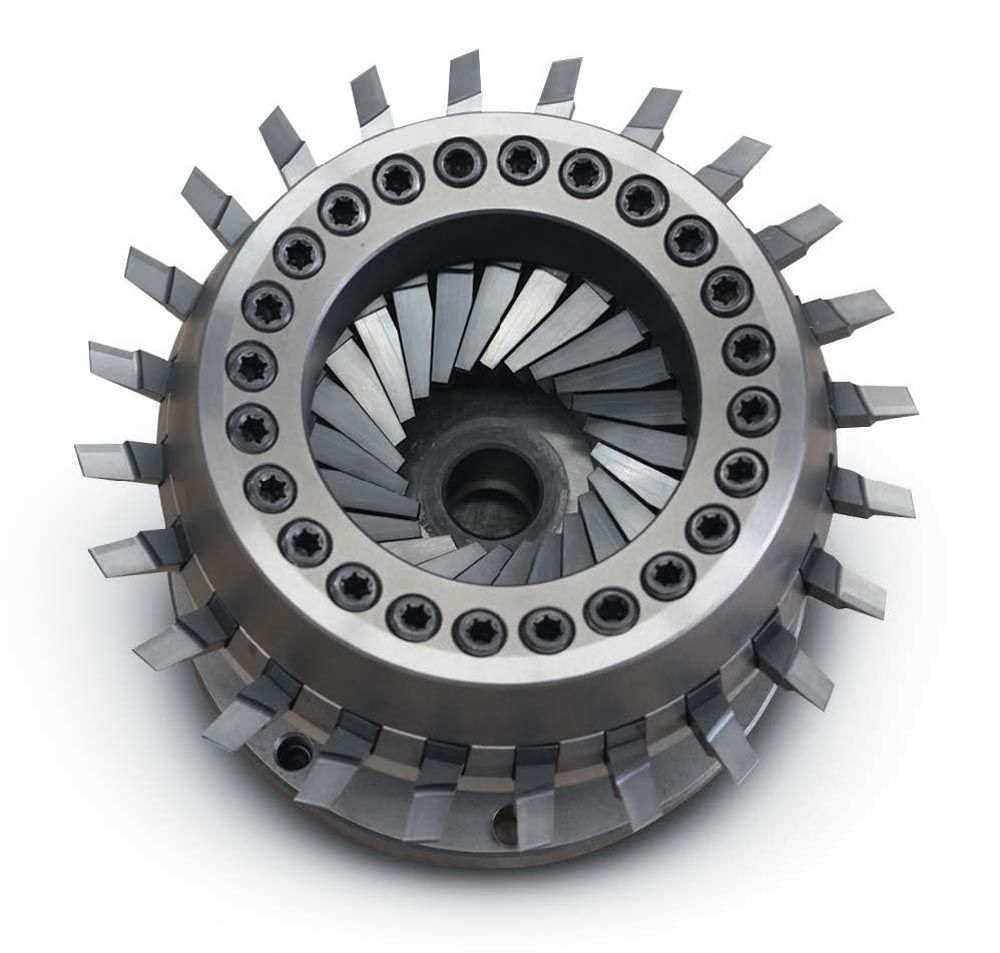
The new process builds on Gleason’s Coniflex Plus high-speed cutter system, using advanced Pentac coated-carbide stick blades, in conjunction with the latest Gleason Phoenix bevel gear cutting machines. Over the years, Gleason’s Coniflex Process for straight bevel gears has steadily evolved, from the ubiquitous mechanical Coniflex Generators to the first application on a new generation of Gleason Phoenix Machines in 2005, to today’s greatly improved Coniflex process, made possible with the development of the Coniflex Plus, the first high-speed dry cutting tool system for manufacturing straight bevel gears. With the Coniflex Plus Cutter Head and the indexing motion of the gearless direct drive work spindle of the Phoenix machines, the production of straight bevel gears was now overall faster compared to the traditional Coniflex Process using HSS blades.
Significantly, with the introduction of Coniflex Plus, manufacturers of differential gears began to see the many benefits of applying this high-quality production technology as an alternative to forged differential gears, particularly in low- to mid-volume applications. Now, with the development and application of Gleason’s Coniflex Pro Design Software, the latest generation of Phoenix Machines and Coniflex Plus Cutter System all operating together in a fully Closed Loop system, we’re proving that differential gears can be readily produced to meet the quality, noise, and productivity requirements of e-drives for automotive, truck, and off-road applications.
The Design Limitations in Forged Differential Gears
Forged differential gears are a good solution for the mass-produced differential of cars and trucks with internal combustion engines. Differentials generally have a high power density because they must fit inside of the differential cage which is inside of the final drive gear. The size of a transmission depends therefore on the size of the differential unit because the transmission is built around it. The severe constraint in size led designers to introduce stiffening webs in the root at the toe and heel, which, in addition to a certain tooth stiffening, also reduces the outer diameter while still maintaining an acceptable wall thickness between the toe and bore. The stiffening webs give a higher root bending strength at moderate loads; however, they also constrain the tooth bending and therefore cause increased sub-surface stresses below the area of the webs which in the case of high loads or shock loads can lead to cracks and flank fracture. The increased tooth stiffness also prevents the desirable small amounts of tooth bending which allows the neighboring teeth to provide a load sharing which reduces the root bending stress.
Forging scale is another undesirable side effect of die forging. In free-form forging the scale flakes off during the forming process. In the case of die forging, the exposure to oxygen is minimized and a high surface pressure is applied. As a result, a very thin scale is formed and becomes a permanent part of the surface structure. The thickness of the scale is between 0.001 to 0.006 mm and is dominated by its ferrite concentration. The forging scale does not form oil pockets like the generating marks of a cut gear. The low relative speeds of differential gears require a certain surface structure to retain some oil film between the contacting tooth flanks which is ideally given by generating marks rather than by a smooth surface. A further obstacle with forged differential gears is the variation in tooth size, indexing and flank form throughout the tool life of the die. This is also reflected in the gear quality according to AGMA or other standards.
Making the case for Coniflex Pro
The new Coniflex Pro Design and Manufacturing System, when integrated into Gleason’s GEMS Bevel Gear Design Software and operating in conjunction with the latest Gleason Bevel Gear Cutting Machines, opens a world of exciting new differential gear design and manufacturing possibilities ideal for e-drive applications—in stark contrast to the inherent limitations of forgings. Coniflex Pro gears are cut in a high-speed, dry PowerCutting process using the Coniflex Plus Cutter System. The cutting blades can be two- or three-faced ground and are preferably all-around coated. Flank form geometry, indexing error, and surface finish of this process are excellent.
With Coniflex Pro, digital flank form information including correction matrixes can be transferred via the Closed Loop network to gear inspection systems and a closed correction loop between measurement and production can be established. Also, the machine summaries for blade grinding, cutting, and grinding are generated in GEMS and can be transferred to the manufacturing machines.
Note, too, that all Coniflex Pro differential gears can, additionally, be ground. Standard differentials might, in extreme cases, see a maximum of 400 rpm relative speed between side gear and planet. For some e-drive designs, the maximal relative differential speed is six times higher, which calls for a hard finishing operation after heat treatment. For that operation, GEMS generates grinding summaries and grinding wheel geometry and design data. The grinding wheels are permanently coated with CBN and can be recoated 6 times which results in low grinding wheel cost per ground part. Cutter head and grinding wheel consolidation between different gear designs are easily possible because the profiles of blades and grinding wheels are simply straight.
Surface Stress and Root Bending: Cut vs. Forged
Since differential gears are subject to significantly higher torque conditions in e-drive applications, this root bending stress and surface stress comparison between Coniflex Pro cut and forged gears, performed with the ANSYS Finite Element Method is illustrative of a major Coniflex Pro benefit as compared to forgings. In this case, a Coniflex Pro differential gearset was designed to replace the originally forged version. STEP files of the cut and forged version had been converted to the ANSYS native format. Also, a model of the side gear spline was created, and the input torque was transmitted from the splined shaft via the internal spline in the side gear bore to the side gear teeth. A rotational constraint was applied to the planetary pinion to create the reaction torque.
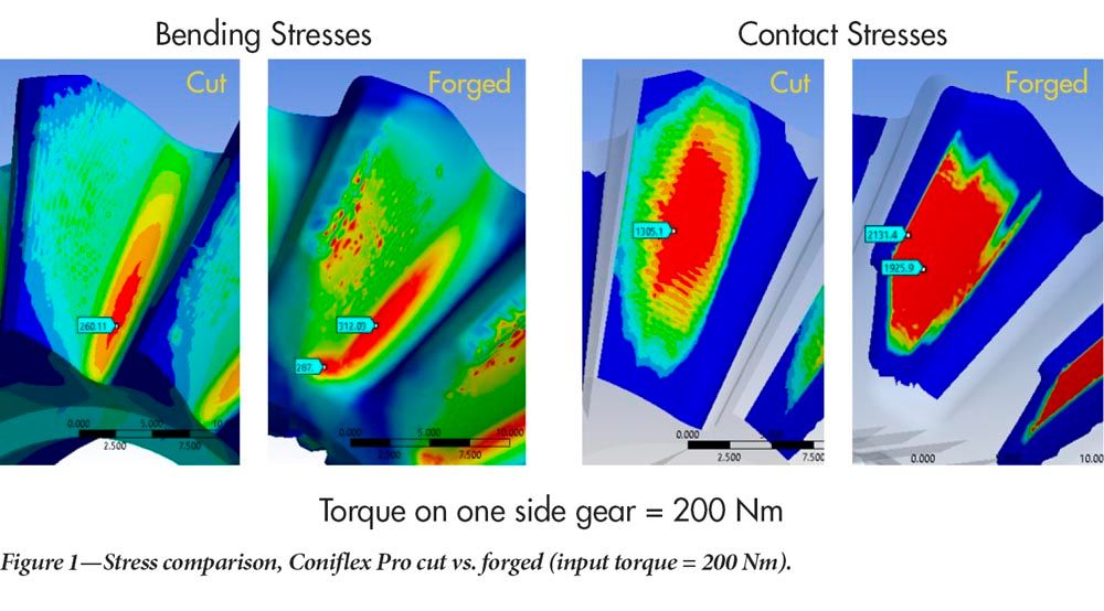
Results for an input torque of 200 Nm are shown in Figure 1. The left two graphics in Figure 1 show the bending stress comparison. The maximum bending stress in the cut side gear is 260 N/mm², compared to 312 N/mm² of the forged side gear. This presents a 20 percent higher bending stress of the forged side gear. It is noticeable that in the toe web area, a high-stress value of 287 N/mm² occurs, compared to about 50 N/mm² of the cut gear in the comparable area. Already with rather low torque, the constrained elastic bending of the forged gear shows a remarkable influence. Larger differences and a sizeable advantage of the cut version become evident in the two right-side graphics of Figure 1 with the comparison of the contact stress. The forged side gear has a 63 percent higher surface stress than the cut version. Also, the fact that the plain profile crowning as was used with the forged differential gear pair results in a nearly straight and abrupt contact pattern cutoff below the tip and above the root transition. In the case of the cut gear, the center contact stress reduces smoothly in all four directions as shown by the color change, from bright red to orange, yellow, green, and blue.
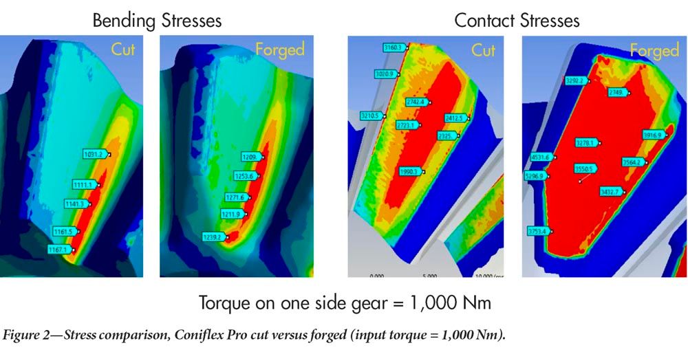
A realistic operating torque of 1,000 Nm was applied in a second calculation. The bending stress results to the left in Figure 2 show a 13 percent to 17 percent advantage of the cut side gear. It is noticeable by the red patch inside of the web area that the web has a high contribution to transmitting the torque. Also, the contact stress to the right in Figure 2 shows up to 65 percent higher values for the forged gear. The especially high value of 3,753 N/mm² in connection with the high bending stress in the same area will result in high sub-surface stresses which can cause case crushing. Case crushing often leads to flank fracture.
Also, for 1,000 Nm torque, the area with high surface stress of the forged version extends to the top land and the toe boundary. In the cut gear, there is also a smooth stress reduction towards the tooth boundaries for 1,000 Nm input torque.
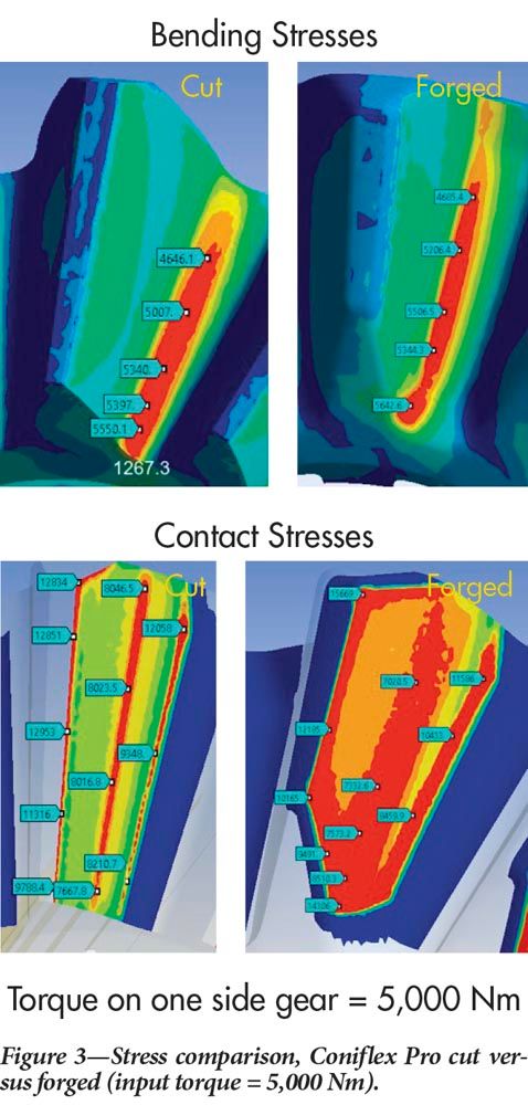
In the third step, the unrealistic high input torque of 5,000 Nm was applied to the cut and forged side gear. Such an extremely high torque will cause stresses in the root as well as on the surface which are well above the allowable material properties, yet it is used in test rigs to simulate shock loads and to record how many revolutions (or fractions thereof) the gearset will sustain. The fracture which consequently will occur is then analyzed with practical conclusions for the potential for failure of the differential during a lifetime load collective.
In Figure 3 the stress results of such a high abuse torque are presented. The graphics for the bending stress results still reflect a 10 percent advantage in bending stress of the cut side gear versus the forged version. Although the forged gear has about the same contact stress values in the heel section, the high-stress area is smaller in profile direction and increases in the web area.
Also interesting is the difference in contact stress. In the heel top area, the forged version has about 22 percent higher stress values. This trend increases in the toe direction, and at the toe the contact stress is even 87 percent higher compared to the cut side gear. These results reinforce the statements made earlier regarding the disadvantage of the webs when high torques are applied and the highest possible power density is required. The linear elastic deflection of the forged teeth is compromised by the webs. One result is the high contact and bending stress concentration in the web area which can result in case crushing and cracks.
Test Rig and Field Testing
Coniflex Pro takes advantage of the geometric and kinematic freedoms available in today’s Phoenix Machines. The advantages of conjugate base geometry and the free control of length and profile crowning with the possibility of a kinematic tip relief are compelling benefits for manufacturers of differential gears for electric vehicles. Although the specific results of actual test rigs and field tests are confidential information of the respective manufacturers, it can be stated that the overall performance of the surface and root of Coniflex Pro gears is potentially up to twice as strong as their forged counterparts.
Finally, NVH (Noise-Vibration-Harshness) properties as confirmed by Fast Fourier Transformation (FFT) testing show that Coniflex Pro differentials roll significantly quieter than forged differentials or differentials cut with the older Revacycle method. To achieve the highest possible power density, all Coniflex Pro differential gears use the duplex taper which has proven highly successful over many years in the well-established Revacycle process. This blank geometry applies an especially high addendum and dedendum angle (10 degrees and more) which results in very strong teeth with the highest strength at the heel where the contact under high load concentrates.
The cutting tools used for Coniflex Pro are Coniflex Plus peripheral cutters with diameters ranging from 9 in. for cars and 15 in. for heavy trucks.
Summary
Coniflex Pro, in initial customer tests, has shown to deliver significant advantages over forgings differential gear manufacturers are greatly in need of, with power density up to two times that of conventional differentials, and quiet-rolling low-NVH properties. It will help to usher in this new age of stronger, quieter, more dependable differential gears for e-drive.