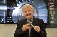
Dr. Hermann J. Stadtfeld received in 1978 his B.S. and in 1982 his M.S. in mechanical engineering
at the Technical University in Aachen, Germany; upon receiving his Doctorate, he remained as a research scientist at the University's Machine Tool Laboratory. In 1987, he accepted the position
of head of engineering and R&D of the Bevel Gear Machine Tool Division of Oerlikon Buehrle AG in Zurich and, in 1992, returned to academia as visiting professor at the Rochester Institute of Technology. Dr. Stadtfeld returned to the commercial workplace in 1994 — joining The
Gleason Works — also in Rochester — first as director of R&D, and, in 1996, as vice president R&D. During a three-year hiatus (2002-2005) from Gleason, he established a gear research
company in Germany while simultaneously accepting a professorship to teach gear technology courses at the University of Ilmenau. Stadtfeld subsequently returned to the Gleason Corporation in 2005, where he currently holds the position of vice president, bevel gear technology and R&D. A prolific
author (and frequent contributor to Gear Technology), Dr. Stadtfeld has published more than 200 technical papers and 10 books on bevel gear technology; he also controls more than 50 international patents on gear design, gear process, tools and machinery.
For cylindrical gears, speed-increasing transmission stages are well known, and regarding profile shift, preferred pressure angles, and helix angles a set of rules applies, which is not much different from the rules for speed reducers. It is important to acknowledge that basically, a speed increaser has to be designed just like a speed reducer, but then the gear with the lower number of teeth is the output. Of course, the torque and the speed of the gear with the lower number of teeth (output) and the gear with the higher number of teeth (input) must be the same as if this transmission was used as a speed reducer. In the case of straight bevel gears, spiral bevel gears, and hypoid gears the same rules apply with some additions. Spiral bevel gears have many applications as speed increasers.
Gleason's Coniflex® Pro Design and Manufacturing System for producing stronger, quieter, and more reliable e-drive differential gears in high volumes, for automotive, truck, bus and off-highway transmissions. It‘s the differential difference!
The conjugacy of meshing gears is one of the most important attributes of gears because it ensures a constant velocity ratio that gives smooth, uniform transmission of motion and torque. Some of the world’s greatest gear theoreticians like Earle Buckingham, Wells Coleman, and John Colbourne laid the foundation for understanding conjugacy. Their teachings and interpretations of the law of gearing have been used by generations of gear engineers to design and manufacture gear transmissions for almost everything that is mechanically actuated.
The fascination of the automotive differential has led to the idea to build a second differential unit around a first center unit. Both units have the same axes around which they rotate with different speeds. The potential of double differentials as ultrahigh reduction speed reducers is significant. Only the tooth-count of the gears in the outer differential unit must be changed in order to achieve ratios between 5 and 80 without a noticeable change of the transmission size.
Chapter 2, Continued
In the previous sections, development of conjugate, face milled as well as face hobbed bevel gearsets - including the application of profile and length crowning - was demonstrated. It was mentioned during that demonstration that in order to optimize the common surface area, where pinion and gear flanks have meshing contact (common flank working area), a profile shift must be introduced. This concluding section of chapter 2 explains the principle of profile shift; i.e. - how it is applied to bevel and hypoid
gears and then expands on profile side shift, and the frequently used root angle correction which - from its gear theoretical
understanding - is a variable profile shift that changes the shift factor along the face width. The end of this section elaborates on
five different possibilities to tilt the face cutter head relative to the generating gear, in order to achieve interesting effects on the
bevel gear flank form. This installment concludes chapter 2 of the Bevel Gear Technology book that lays the foundation of the following
chapters, some of which also will be covered in this series.
In the previous sections, the development of conjugate bevel gearsets via hand calculations was
demonstrated. The goal of this exercise was to encourage the reader to gain a basic understanding of
the theory of bevel gears. This knowledge will help gear engineers to better judge bevel gear design
and their manufacturing methods.
In order to make the basis of this learning experience even more realistic, this chapter will convert
a conjugate bevel gearset into a gearset that is suitable in a real-world application. Length and profile
crowning will be applied to the conjugate flank surfaces. Just as in the previous chapter, all computations
are demonstrated as manual hand calculations. This also shows that bevel gear theory is not as
complicated as commonly assumed.
This article is the fourth installment in Gear Technology's series of excerpts from
Dr. Hermann J. Stadtfeld's book, Gleason Bevel Gear Technology. The first three
excerpts can be found in our June, July and August 2015 issues.
In the previous chapter, we demonstrated the development of a face-milled spiral bevel gearset. In this section, an analogue face-hobbed bevel gearset is derived.
The calculation begins with the computation of the ring gear
blank data. The geometrically relevant parameters are shown in Figure 1. The position of the teeth relative to the blank coordinate system of a bevel gear blank is satisfactorily defined with...