
A New Process for Differential Gear Manufacturing
Enhancing strength, efficiency and quiet performance for electric vehicles
The manufacturing of differential gears went away from the Revacycle broaching process to forging more than 30 years ago. Today, where electric vehicles create a peak torque which are a multiple higher than in vehicles with internal combustion engines, the strength and the Noise Vibration Harshness (NVH) advantages of cut differential gears are revisited. The newly developed Coniflex Pro straight bevel gears combine several new features which make them stronger and quieter than past straight bevel gears and far superior to the forged version. The basic geometry of Coniflex Pro was developed especially for modern Phoenix free-form CNC machines and takes advantage of the “unlimited” geometric freedoms and the possibility of higher order, nonlinear kinematics. First field applications have proven that Coniflex Pro differentials have 30 percent lower root bending stress and 40 percent lower surface stress as forged differential gears. Many electric all-wheel drive vehicle applications with a front axle disconnect feature create high relative motions in the differential of the disconnected axle, which makes the transmission very noisy. Coniflex Pro gears have the lowest transmission error of any ever-produced straight bevel gear. While transmission errors of 50 microradians (µrad) or less are typical for Coniflex Pro, conventionally cut or forged straight bevel gears show between 300 and 2,000 µrad. Coniflex Pro differentials are therefore exceptionally quiet, even in case of high relative motions in disconnect axles.
Generating on the Pitch Cone
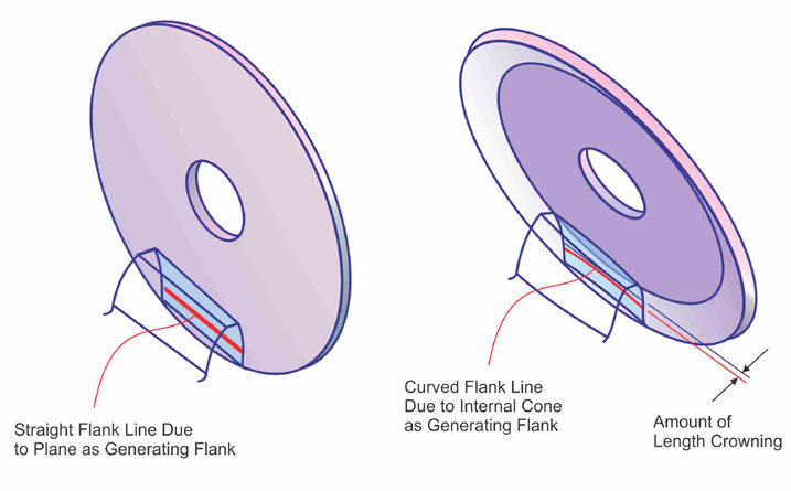
All the older straight bevel gears are generated by rolling on the root cone, rather than on the pitch cone. Figure 1 shows to the left the traditional orientation between the generating plane and the pitch cone of a gear. This orientation violates the kinematic coupling condition between gear, generating plane and pinion. Both mating Coniflex Pro members roll with their pitch cones on the common generating gear plane as shown to the right in Figure 1. This was not possible in the past because the tip circle of the cutting tool had to be adjusted to the root angle of the tapered depth teeth of the gears and due to the mechanical restrictions of older machines, the generating gear rotation was automatically orthogonal to the root line of the cut gear. Thus, the gears were generated on the root cone rather than on the pitch cone.
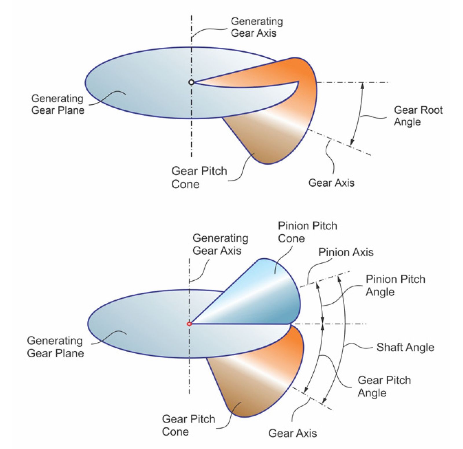
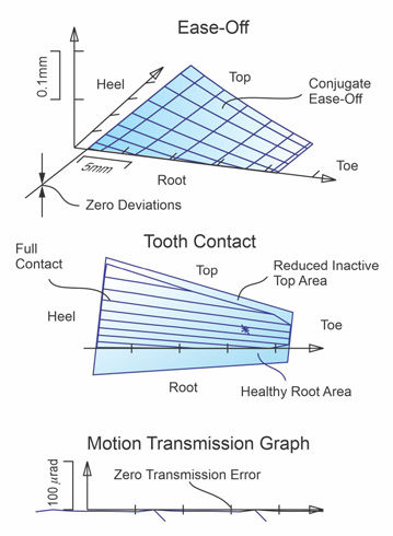
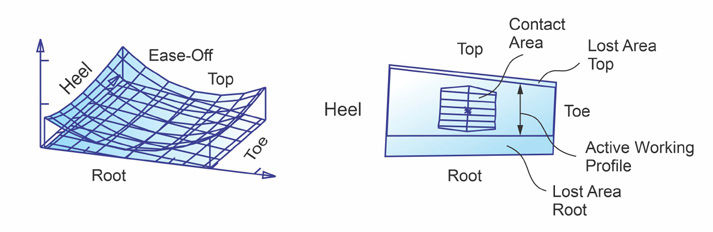
Free-form Phoenix machines do not have the traditional mechanical restrictions. Therefore, the choice of adjusting the cutter tip circle tangential to the root line of the cut pinion and gear and yet performing a roll motion around a generating gear axis perpendicular to the gear’s pitch cone has become possible with Phoenix machines. The result is a perfectly conjugate interaction between pinion and gear, like shown in the contact analysis in Figure 2. The ease-off topography is zero and the tooth contact extends over the entire working area. The motion transmission error has a slight numerically caused variation but is practically zero. To prepare a gear set for manufacturing tolerances and deflections under load, length crowning can be created with a dished cutter as shown in Figure 3 and profile crowning can be created with a second order ratio of roll modification (Figure 4 bottom graphic).
Tip Relief
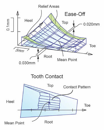
The tooth profiles of a high-power density differential gear set should be conjugate in the center and feature a pre-determined tip relief. A new function in Coniflex Pro allows creating a higher order tip relief which preserves a low transmission error and protects better against edge contact as the traditional circular profile crowning. A typical Coniflex Pro tooth contact analysis is shown in Figure 5. The Ease-Off has higher order relief areas along tip and root. The flank center around the Mean Point is nearly conjugate and the tooth contact is full and centered. The motion transmission graph in Figure 5 shows very small amplitudes of 25 µrad (compared to the traditional 300 to 2,000 µrad).
Double Positive Profile Shift
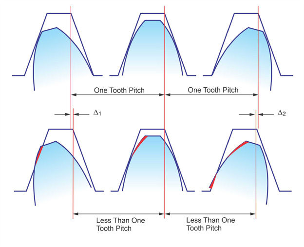
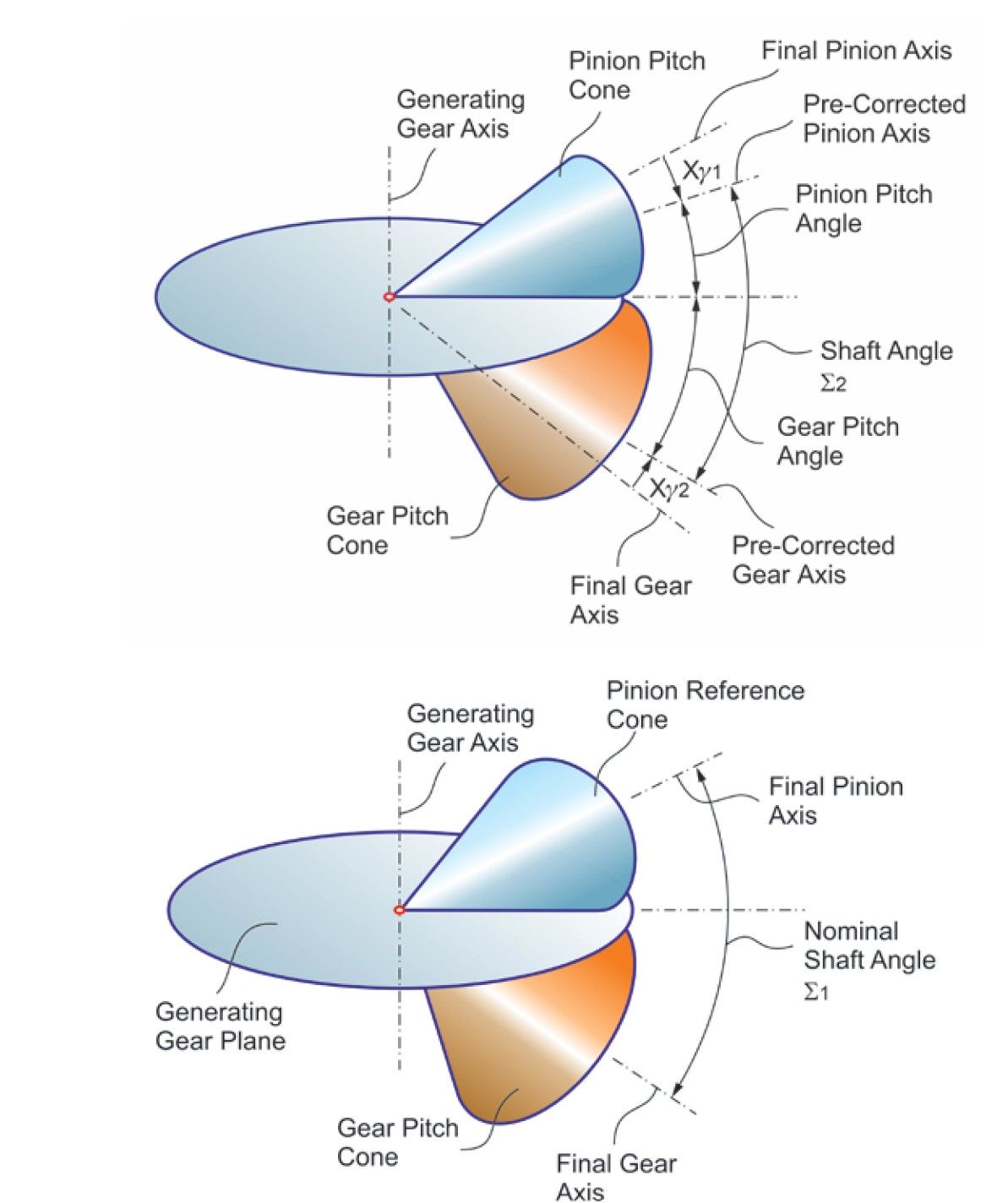
Until now, in bevel and hypoid gears, the same amount of positive profile shift used to reduce pinion undercut had to be applied to the gear, but with a negative sign. This was required to maintain the desired shaft angle. For differential gears, where the gear has also a low number of teeth, the profile shift had to be limited to small amounts to avoid undercutting the gear teeth. The newly developed independent profile shift allows positive profile shift for pinion and gear which results in stronger tooth profiles and increases the contact ratio by up to 50 percent. The principle is shown in Figure 6. Pinion and gear pitch cones are smaller by the equivalent amount of desired profile shift which reduces the shaft angle: Σ1 – Xγ1 – Xγ2 = Σ2 (Figure 6 left side). After the profile shift is applied, the reference pitch cones (working pitch cones) include the correct shaft angle Σ1 (Figure 5 right side) and the gear set has the advantages of a positive profile shift in both members. To demonstrate the dramatic improvement of this technology, the tooth contact of a differential gear set without profile shift is shown in Figure 7. The tooth contact of the same gear set with double positive profile shift X1 = X2 = +0.7 is shown to the right in Figure 7. The contact pattern increased in profile direction by about 30 percent. The result is an increased contact ratio, a reduced root bending stress and a reduced flank surface contact stress.
Stress Comparison Coniflex Pro vs. Forged
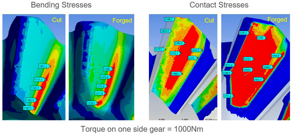
A root bending stress and surface stress comparison between Coniflex Pro cut and forged gears was performed with the ANSYS Finite Element Method. The Coniflex Pro differential gear set was designed to replace the originally forged version. Also, a model of the side gear spline was created, and the input torque was transmitted from the splined shaft via the internal spline in the side gear bore to the side gear teeth. A torque of 1,000 Nm, which reflects the duty cycle peaks of a midsize EV, was applied. The bending stress results to the left in Figure 8 show a considerable advantage of the cut side gear (i.e., the cut pair). It is noticeable by the red patch inside of the web area at the toe that the web restricts the necessary tooth deflection in this critical area, resulting in twice the bending stress of the cut gear. The high load contact area in the right-side graphics (red) fades out smoothly on the Coniflex Pro cut gear but extends to tip and root on the forged version. This proves the advantageous function of the Coniflex Pro tip relief. Also, the contact stress magnitudes in Figure 8 show up to 65 percent higher values of the forged gear. The especially the high value of 3,753N/mm² in connection with the high bending stress in the same area will result in high sub surface stresses which can cause case crushing. Case crushing often leads to flank fracture.