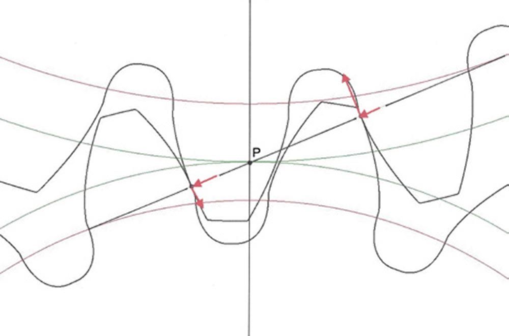
Figure 2—Contact at two points in the double-pair zone in the transverse plane (Ref. 4).
Helical Gears
Figure 3 shows helical gear velocities in the tangent plane. The tangent plane is perpendicular to the contact plane or surface of action. The tangent plane contains the contact line and is perpendicular to the common normal of the contacting teeth. The contact line is located at the intersection of the tangent plane and the contact plane. The red line labeled zo is a general coordinate in the normal plane that locates the contact point Q from pitch point P on the pitch element.
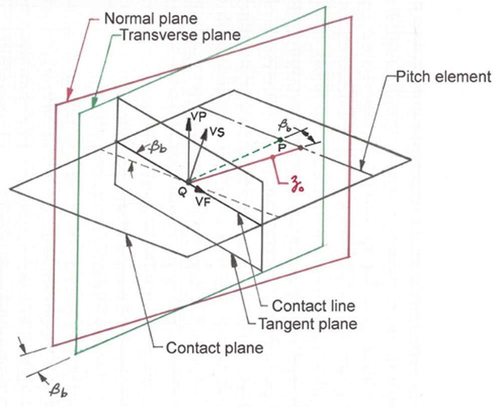
Figure 3—Helical gear velocities in the tangent plane (Ref. 4).
Figure 4 shows contact point Q at a distance zo from pitch point P on the pitch element in the normal plane. Distance zo is a general coordinate, that locates point Q in the normal plane (zo is positive to the left of P and negative to the right of P). Figure 4 shows the contact point Q at the tip of the pinion tooth where the sliding velocities are often maximum.
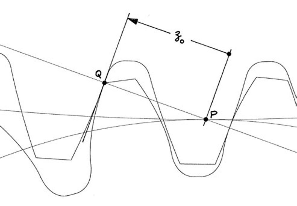
Figure 4—Contact point Q at distance zo from pitch point P in the normal plane (Ref. 3).
Figure 5 shows helical gear sliding velocities VP, VF, and VS at point Q in the tangent plane. It is well known that helical gears have no sliding in the axial direction. However, there is sliding along the contact line in the tangent plane represented by velocity VF.
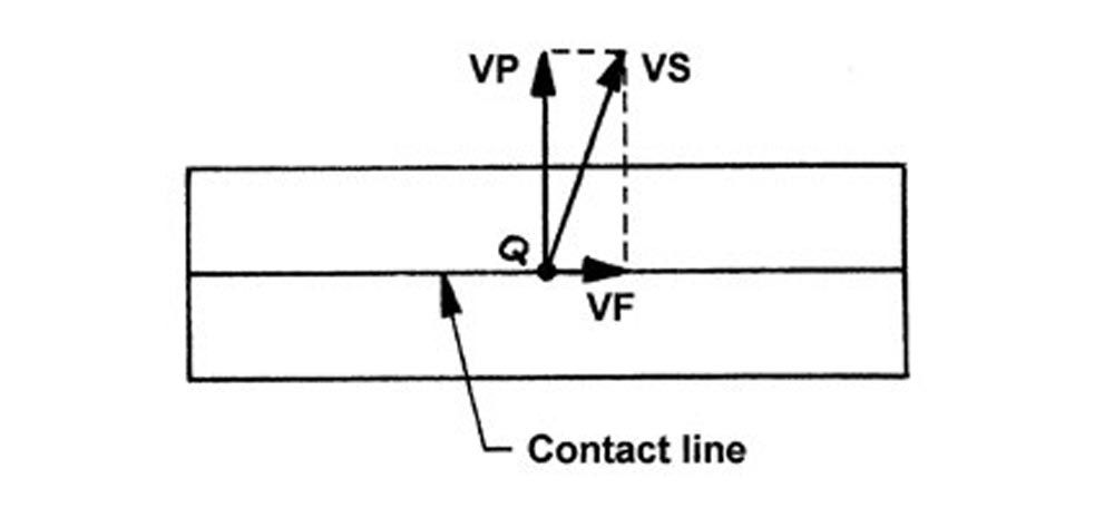
Figure 5—Helical gear velocities VP, VF, and VS at point Q in the tangent plane (Ref. 4).
Table 1 shows sliding velocities calculated with the Mathcad program given in GEARTECH Report (Ref. 4). The equations are from Wells Coleman (Ref. 2). The example is for module 10 helical gears operating at 10,000 rpm and 131 m/s pitch line velocity.
Table 1—Sliding velocities per Refs. 2,4 |
β (deg) | VF (m/s) | VP (m/s) | VS (m/s) |
0 | 0.000 | 31.140 | 31.140 |
10 | 1.862 | 30.882 | 30.938 |
15 | 2.800 | 30.551 | 30.679 |
20 | 3.743 | 30.071 | 30.303 |
30 | 5.647 | 28.599 | 29.151 |
45 | 8.471 | 24.767 | 26.176 |
Figure 6 shows how the sliding velocities VF, VP, and VS vary with helix angle. Note that the calculations were performed for point Q at the pinion tooth tip, which is often the point of maximum sliding velocities. However, depending on the pinion profile shift, the point of maximum sliding velocity might be at the other end of the path of contact.
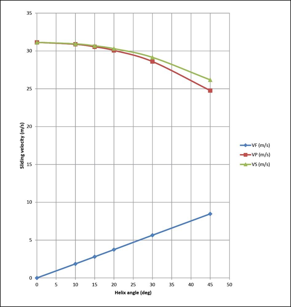
Figure 6—Sliding velocities per reference (Refs. 2,4).
Comparison of Helical Gears and Spur Gears
Helical gearing is essential when tooth-to-tooth transmission smoothness (low transmission error) is required. The smooth running characteristic of helical gears is achieved because all phases of tooth meshing occur simultaneously provided that the face width is large enough to give an axial contact ratio (overlap ratio) greater than unity. In contrast, spur gears have alternating single-pair and double-pair tooth contact that results in much higher transmission error. Furthermore, the resulting stiffness variation causes a nonlinear dynamic response, which increases the risk of resonant vibration that results in much higher dynamic tooth loads. Consequently, audible noise and vibration levels are much higher with spur gears than with helical gears.
Helical gears are capable of very high speeds with pitch line velocity approaching 200 m/s. However, such high speed requires very sophisticated design practice, which includes analyses of temperature rise due to sliding in gears and bearings, windage between gear teeth and the gearbox internal environment, and shearing of lubricant films in gears and bearings. Furthermore, as gear teeth mesh at high speed the air/oil mist in the space between teeth must be expelled by meshing teeth. Helical gears pump the air/oil mist in the axial direction much more efficiently than spur gears. This is the primary reason that spur gears have much lower speed limits than helical gears. On the other hand, the axial pumping velocity of helical gears with low helix angles can be very high (reaching Mach 3), which causes thermal bulging of the gear teeth. Therefore, helical gears with pitch line velocity greater than 100 m/s usually require curvilinear helix modification to compensate for thermal bulging.
Crossed-Axis Helical Gears (Colbourne)
The following analysis is based on Chapter 15, pages 414–429 of Colbourne (Ref. 3).
Requirements for Conjugacy
To be conjugate, the normal base pitches of each crossed-axis helical gear must be the same. This is the only requirement that must be met for conjugacy.
pnb1 = pnb2
Center Distance
The center distance is the line joining the axes, which is perpendicular to both axes and is the shortest distance between the axes. See Figure 7. The center distance is the line C between the points on the axes Co1 and Co2. If an imaginary rack is inserted between the teeth of both gears, it touches the pitch cylinders of the gears in two parallel pitch planes. Crossed-axis helical gears are generally designed so that the values of C and Σ are either equal or approximately equal, to the reference (standard) center distance Cs and reference (standard) shaft angle Σs.
Cs = Rs1 + Rs2
Σs = ψs1 + ψs2
For the particular case where the center distance equals Cs, the shaft angle must equal Σs to maintain conjugacy.
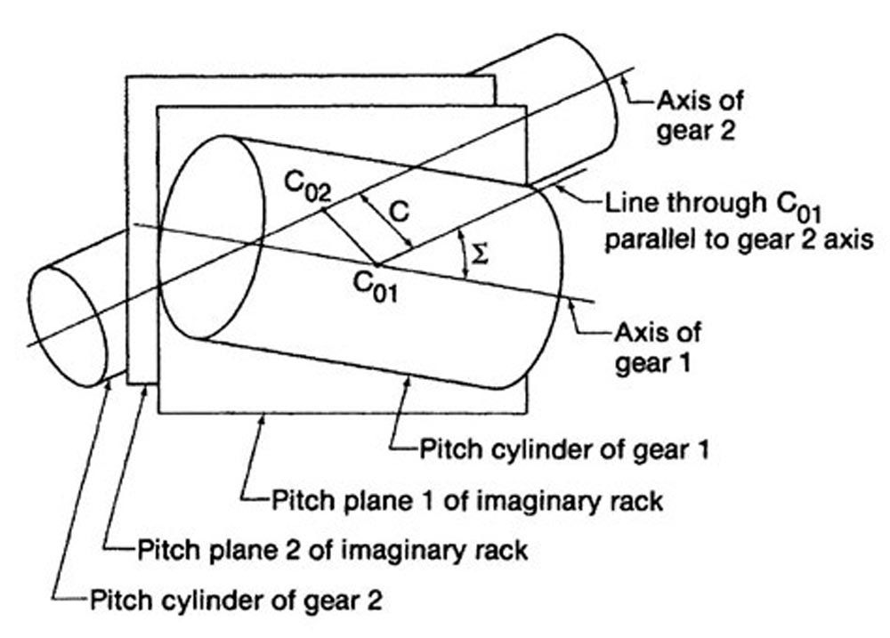
Figure 7—Pitch cylinders in a crossed-helical gear pair (Ref. 3).
Shaft Angle
Figure 8 is a view in the direction of the line of centers. The shaft angle equals the sum of the two working helix angles.
Σ = ψp1 + ψp2
Because crossed-axis helical gears have point contact, they are not sensitive to shaft angle, and they remain conjugate even with small errors in Σ.
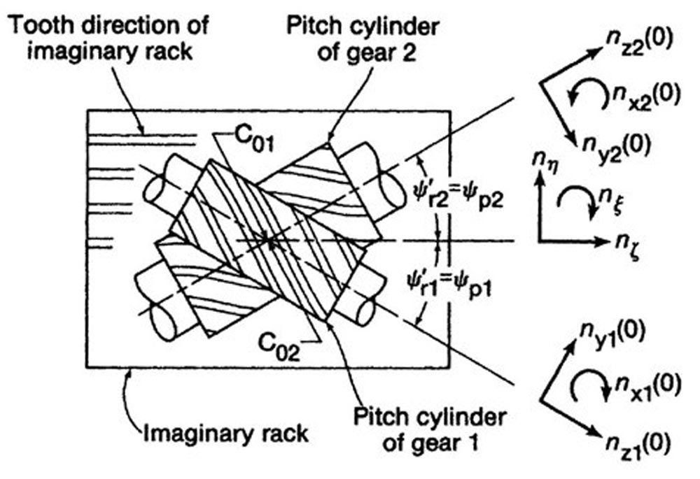
Figure 8—Directions of the unit vectors (Ref. 3).
Pitch Planes
The two pitch cylinders and the imaginary rack pitch planes are shown again in Figure 9, but viewed this time in the negative nη direction, which is perpendicular to the teeth of the imaginary rack.
The center distance is not necessarily equal to the sum of the pitch cylinder radii. Figure 9 shows an example where the pitch planes of the imaginary racks are separated by the distance ΔCp.
ΔCp = C - Rp1 – Rp2
There is no relation between the pitch cylinders and the center distance C, Therefore, the pitch cylinders do not touch, and there is no point of pure rolling.
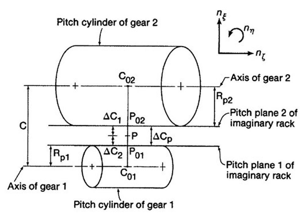
Figure 9—Pitch cylinders perpendicular to teeth of the imaginary rack (Ref. 3).
Pitch Points
Figure 10 shows that the path of contact is a straight line that coincides with the line of action, exactly as it does in the case of a spur gear pair. The path of contact is inclined at the working normal pressure angle to the pitch planes of the imaginary racks and intersects the points P1 and P2 on the pitch planes.
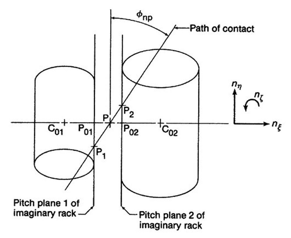
Figure 10—Pitch cylinders viewed along the teeth of the imaginary rack (Ref. 3).
Analogy to a Spur Gear
When the pinion is viewed in the axial direction, as shown in Figure 11, the path of contact appears exactly the same as the path of contact in a spur gear pair. The straight line containing the path of contact extends from a typical contact point A1, passes through the pitch point P1, and touches the base cylinder at point E1.
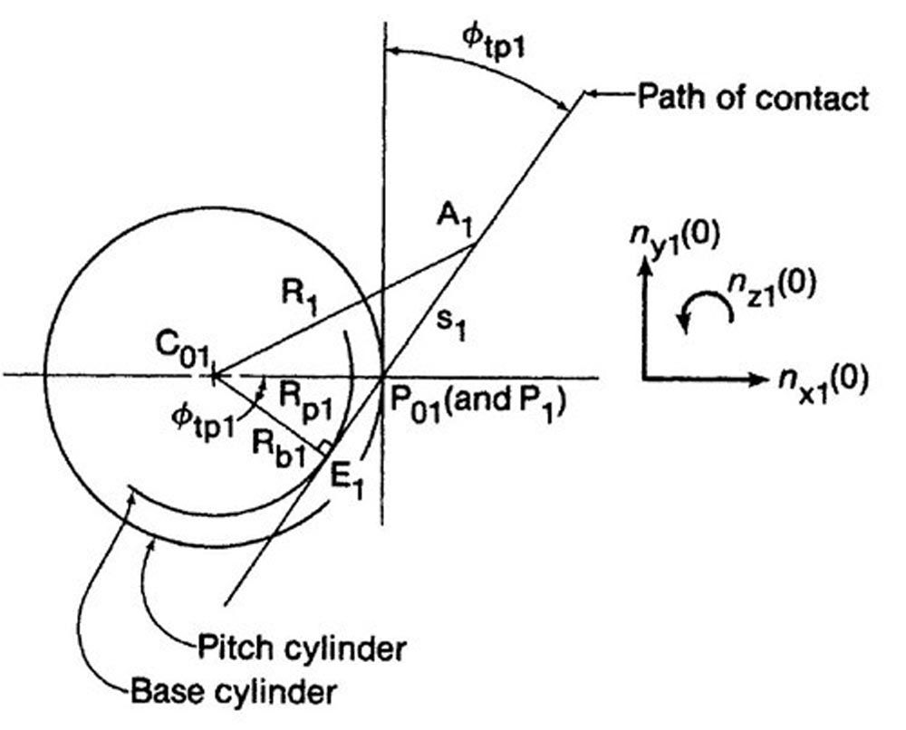
Figure 11—Pitch cylinder of gear 1 viewed along the gear axis (Ref. 3).
Crossed-Axis helical gears (ISO 21771-1:2022)
Figure 12 is based on Figure 32 of ISO 21771-1:2022 (Ref. 5). ISO nomenclature is somewhat different from the nomenclature of this paper. Therefore, certain terms are defined here:
C = P Pitch point in the normal plane
C1 = Pinion pitch point in the transverse plane
C2 = Gear pitch point in the transverse plane
Cn = Pitch point in the tangent plane
Line T1 – T2 = Line of action that passes through the pitch point C = P in the normal plane
Comparison of Helical Gears and Crossed-Axis Helical Gears
Parallel-axis helical gears have contact lines similar to that of parallel cylinders, which take place along straight line generatrices, similar to spur gears, but the lines of contact slope instead of remaining parallel to the axis of the gear. Crossed-axis helical gears have contact lines similar to two cylinders whose axes are not parallel. With axes crossed at 90 degrees, and under near zero load, point contact occurs. At less than a 90-degree shaft angle, and at working load, the contact spreads to an elliptical contact area. Hertzian stress in crossed-axis helical gears with point contact is very much higher than that of parallel-axis helical gears with line contact.
Point contact occurs in crossed-axis helical gears because the straight generatrix of each involute helicoid are tilted relative to each other and cross at a single contact point. With a rotation of the gears, the contact point travels in a straight path of contact in the normal working plane as shown by the line between points A and E in Figure 12.
A high sliding velocity, equal to the vector difference of the two pitch line velocities, is present at all phases of tooth engagement of crossed-axis helical gears. A third vector normal to the other two adds a component of sliding velocity similar to that which occurs in parallel-axis helical gears. This third vector has zero magnitude when contact is at the pitch point and is a maximum when contact is at its furthest point from the pitch point.
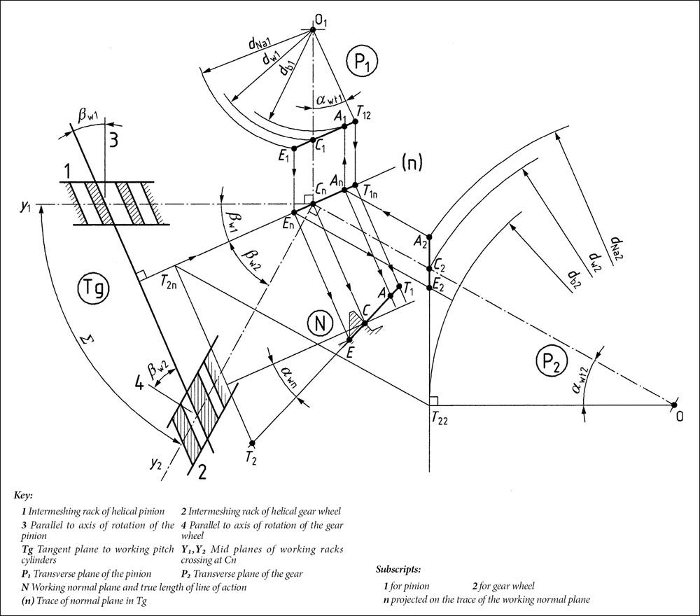
Figure 12—Meshing conditions in transverse planes and working normal plane (Ref. 5).
Because of point contact, crossed-axis helical gears are insensitive to changes in center distance, changes in shaft angle, or changes in the axial position, and they remain conjugate even with reasonably small mounting errors. Furthermore, crossed-axis helical gears are among the easiest to manufacture, which makes them among the least expensive gears. Despite all these advantages, the gear designer must consider that the load capacity of crossed-axis helical gears is severely limited because of the point contact.
Worm Gears
The following three paragraphs are from Buckingham (Ref. 1):
- “The conjugate gear-tooth action between a worm and a worm gear is the same whether the worm is revolved to screw the thread along its axis or whether the worm is moved axially without revolving.”
- “The basic-rack form of the worm gear is the form of that section of the worm thread which actually engages with the worm-gear teeth. This form changes across the face of the worm gear. When these forms are established for any given planes of rotation of the worm gear, conjugate gear tooth forms and trochoidal fillets of the worm gear are determined for these planes of rotation in exactly the same manner as for spur gears.”
- “The essential requirement is that the thread form of the worm and that of the hob or other tool used to generate the worm gear be as nearly identical as possible.”
Buckingham’s statements mean that the conjugacy requirements of worm gearsets are the same as that of a spur gear meshing with its basic rack.
Buckingham (Ref. 6) gives the calculation procedure for contact analysis of worm gear drives in Chapter 11, on pages 240–255. The procedure is as follows:
- The profile of the intersection of the worm thread on planes parallel to the worm axis forms the basic rack profile in the axial plane of the worm.
- Using tangents to the basic rack profiles, coordinates of the path of contact are calculated for each basic rack profile.
- The rack profiles and their paths of contact are then plotted from the calculated data. Where a path of contact intersects its rack profile, it defines one point of contact between the worm and its mating worm gear.
- Several points of contact thus determined are projected into the plan view of the worm to their respective traces of intersecting plane and are then connected with a smooth curve. This curve is the projection of the actual contact line on the plan view of the worm.
- These same points of contact on the rack profiles are also transferred or projected into the end view of the worm to their respective sections. These points, when connected by a smooth curve, give the projection of the actual contact line on the end view of the worm.
The following three figures give the results of an example from Buckingham’s contact analysis of a screw helicoid worm drive (Ref. 6).
Figure 13 shows the end view of a screw helicoid worm. Five axial planes A, B, C, D, and E were selected for the analysis. Distance R1 locates the height of the pitch plane of the worm above its axis. Angles εE and εA are generatrix rotation angles.
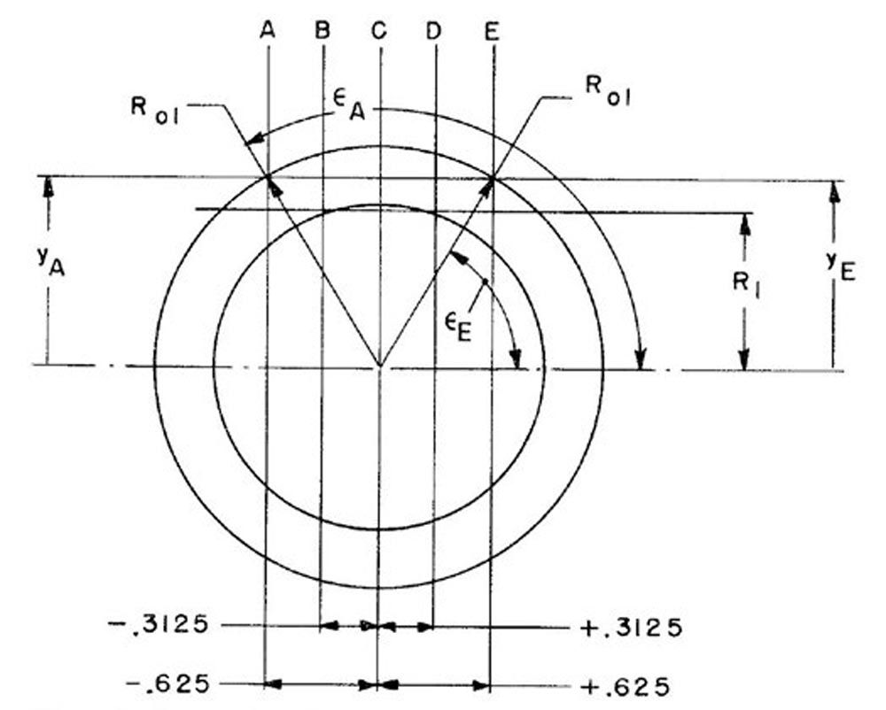
Figure 13—Axial planes, pitch plane, and generatrix rotation angle (Ref. 6).
Figure 14 shows the paths of contact for the axial planes A, C, and E. The rack profile for section C is the generatrix of the helicoid. The intersection between rack profile C and the worm axis is shown after the worm has moved along the worm axis at a distance equal to one-quarter of the lead because it has revolved 90 degrees or one-quarter of the full circle. The intersection of path C with rack profile C locates a contact point between the worm and worm gear. Sections A and E are at the side edges of the worm gear. For section A, the path of contact is outside the rack profile and therefore the contact point is nonexistent. For section E, the contact point is below the pitch plane and beyond the outside radius of the worm gear. Therefore, the contact point is non-existent.
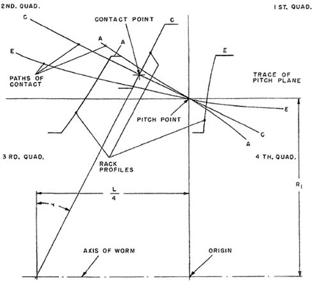
Figure 14—Paths of contact for sections A, C, and E (Ref. 6).
The lower right side of Figure 15 shows a repeat of the Figure 14 paths of contact, but it adds the rack profiles and paths of contact for sections B and D. The outside radius of the worm gear R2, which is also the gear pitch radius, is also shown.
The upper area of Figure 15 shows a plan view and projected field of contact on the worm. The space between the lines marked “root” and “crest” represents the flank of the worm thread on which contact will exist. Contact lines marked 1 and 2 exist on adjacent teeth.
The lower left side of Figure 15 shows the end view of the worm with the projected points from the paths of contact plotted to show the contact lines 1 and 2 on the flanks of adjacent worm teeth.
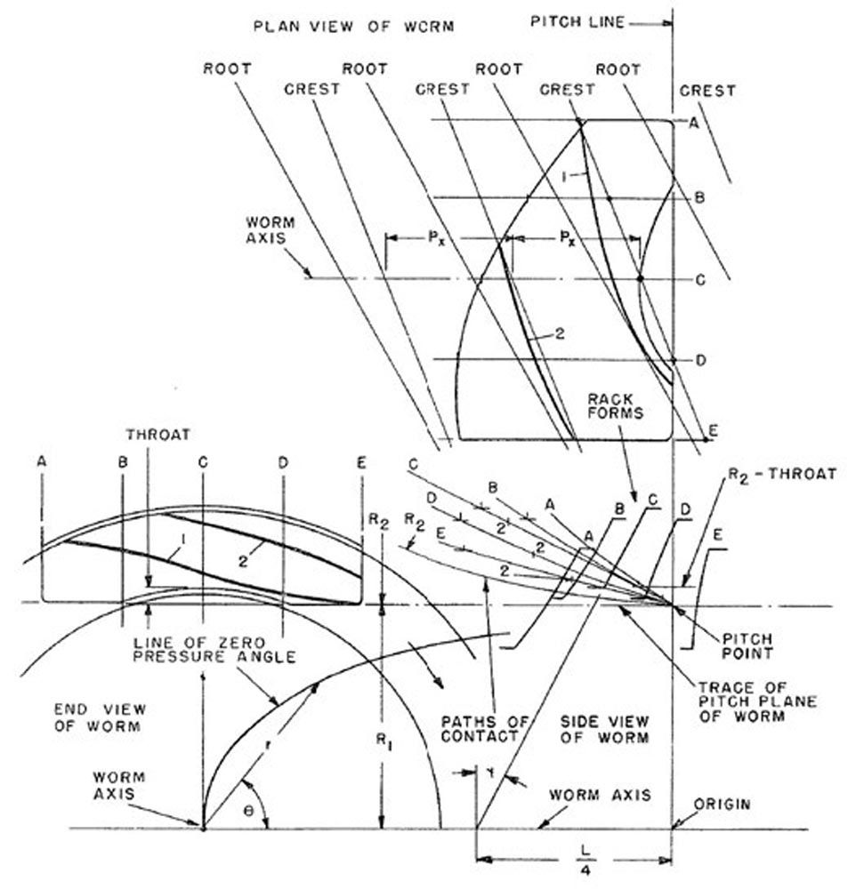
Figure 15—Paths of contact, the field of contact, and contact lines (Ref. 6).
Comparison of Crossed-Axis Helical Gears and Worm Gears
Crossed-axis helical gears are sometimes confused with worm gears. This is probably because a standard single-start worm can mesh properly with either a standard spur gear or a standard helical gear. When the worm thread is an involute helicoid and the gear is a helical gear, the gear pair is an example of crossed-axis helical gears. There will be true conjugate action, but there will be point contact and low load capacity.
The most common worm gear drive consists of a cylindrical worm (not necessarily with an involute helicoid thread) and an enveloping worm wheel. This is called a single-enveloping worm drive. As discussed in the worm gear section, this combination has line contact in place of the point contact that exists in crossed-axis helical gears. Consequently, a worm drive with a cylindrical worm and an enveloping worm wheel has a much higher load capacity than a crossed-axis helical gear drive. However, many of the advantages of crossed-axis gears such as insensitivity to mounting errors are lost with a worm gear drive.
A double-enveloping worm drive consists of an “hourglass” worm and a throated worm wheel. As the name double-enveloping implies, the worm and the wheel “wrap around” each other. A double-enveloping worm drive has line contact with more teeth in contact and higher load capacity than a single-enveloping worm drive. However, the axial alignment of the worm and wheel in a double-enveloping worm drive is more critical. Furthermore, manufacturing costs are higher than a single-enveloping worm drive.
Bevel Gears (Ref. 7)
Figure 16 shows the conical pitch surfaces of a bevel gearset. Bevel gears have pitch cones that contact along the pitch element. The pitch apexes coincide at the intersection of the axes of the shafts. The pitch point P is on the connecting line normal to the pitch element and intersects the shaft axes at crossing points no1 – no2.
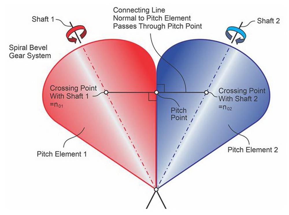
Figure 16—Bevel shaft axes connecting line, pitch point P, and pitch surfaces (Ref. 7).
Figure 17 shows that the base surfaces of bevel gears are cones whose cone apexes coincide at the intersection of the axes of the shafts. In analogy to cylindrical gears, the line of action is straight and is tangent to the two base circles at a respective location along the width of the cones. If the line of action is shifted along the width of the base cones, the plurality of the lines of action forms the surface of action, which is a plane. This occurs because of the equal and proportional change of the respective base circles while the line of action is shifted. When viewed in the direction of the pitch element, the plane of action appears as a line, like that shown in the two right-side graphics in Figure 17.
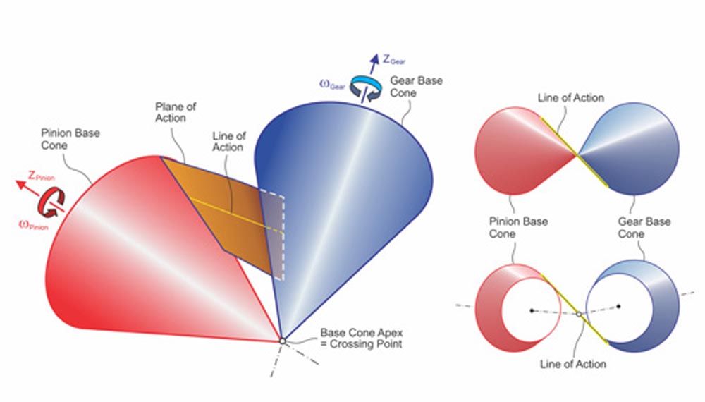
Figure 17—Bevel base cones, the plane of action, and line of action (Ref. 7).
Comparison of Straight Bevel Gears and Spiral Bevel Gears
This comparison is very analogous to the comparison between spur gears and helical gears. The spiral angle results in a face contact ratio larger than zero. The modified contact ratio considers both the transverse contact ratio and the face contact ratio. Typical modified contact ratios of spiral bevel gears are between 2.0 and 2.5. Straight bevel gears cannot achieve modified contact ratios greater than 1.5 because the face contact ratio is always zero. Therefore, spiral bevel gears have a smoother and quieter operation than straight bevel gears.
Straight bevel gears have the significant advantage of the largest possible root thickness for a given module. In the case of bevel gears that are heat treated after cutting but not hard finished, the root bending strength of a spiral bevel gearset would be rather low. The tooth indexing errors resulting from heat treatment distortions reduce the real contact ratio in the operation, so the benefit from the spiral angle diminishes, but the disadvantage from the smaller tooth root thickness remains. This leads manufacturers that do not apply hard finishing to their bevel gears to prefer straight bevel gears.
Straight bevel gears are also preferred in cases when the bearing forces must be low. Many aircraft gear manufacturers apply ground straight bevel gears for the actuation of wing flaps and other components, but they prefer ground spiral bevel gears for power transmission such as the main rotor drives in helicopters.
Hypoid Gears (Ref. 7)
Conjugacy between a hypoid pinion and a hypoid gear is established when the hyperbolic pitch surfaces are designed as explained in Figure 18. The screw axis is the axis of a cylinder, on whose surface the pitch generator line “g” is found as the plurality of points where the shaft connecting line nop – nog passes through the cylinder and is normal to the cylinder. When line “g” is rotated around the pinion axis Za, it generates the pinion pitch surface. When rotated around the gear axis Zb, it generates the gear pitch surface. After one or both pitch surfaces are found, the shaft connecting line nop – nog is added. It describes the location of the pitch point “P” where the connecting line passes through the two contacting pitch surfaces.
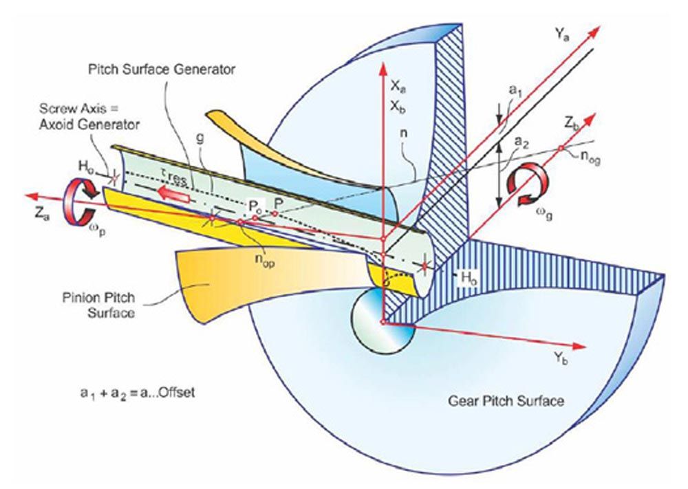
Figure 18—Hypoid shaft connecting line, pitch point P, and pitch surfaces (Ref. 7).
Figure 19 shows the hypoid gear base surface and the surface of action. The surface of action connects the base surface of the pinion and the gear and contacts both base surfaces tangentially. Because the base surfaces are also hyperboloids, the surface of action is not a plane, but a warped surface.
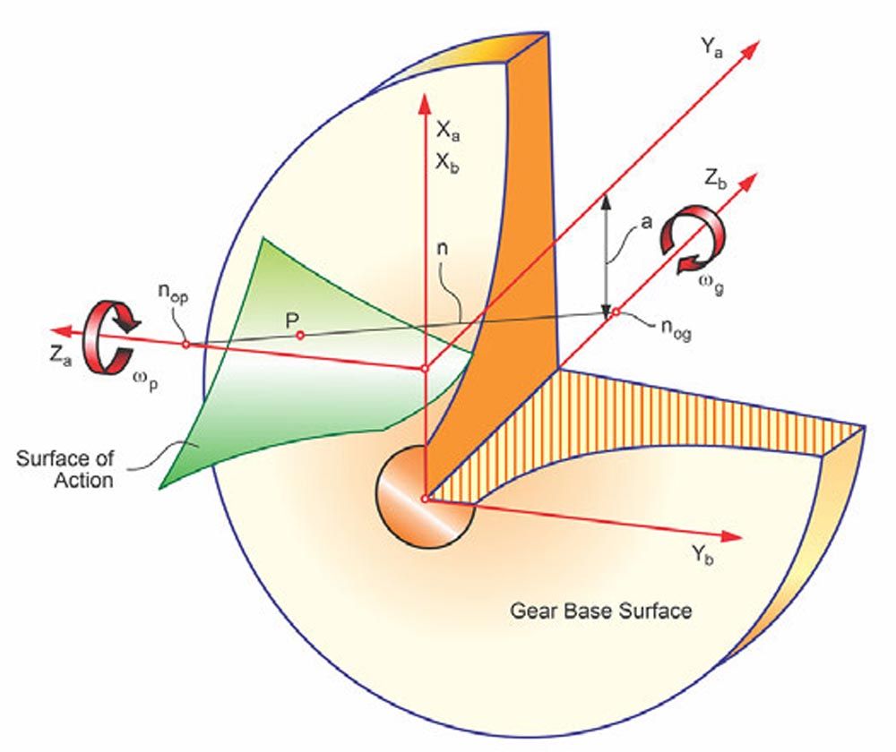
Figure 19—Hypoid gear pitch surface and surface of action (Ref. 7).
Comparison of Bevel Gears and Hypoid Gears
The original intention of the development of hypoid gears by Ernest Wildhaber was to provide the additional design freedom of a pinion shaft offset in bevel gearing. This freedom allowed the automotive manufacturer in the 1920s to lower the bodies of their vehicles by up to two inches. The lower center of gravity of these vehicles provided more safety and better handling in the early vehicles. Still, today, rear-wheel and all-wheel drive vehicles use hypoid gears for this reason.
The hypoid offset increases the pinion spiral angle, which leads to a pinion diameter increase of up to twice the diameter of a spiral bevel pinion. The size increase strengthens the hypoid pinion, which for spiral bevel gears is the weaker of the two members. In addition to the sliding velocities in the profile direction, hypoid gears have a screw motion between pinion and gear, which creates sliding velocities in the face-width direction. These lengthwise sliding motions can be two to three times in magnitude compared to the profile sliding. The lengthwise sliding provides several advantages. The elastohydrodynamic lubrication film is not compromised at the pitch line, where spiral bevel gears exhibit pure rolling and no sliding. The lengthwise sliding also provides a dampening effect, which in combination with the larger pinion spiral angle makes hypoid gearsets operate quieter.
The disadvantage of lengthwise sliding is that it limits the pitch line velocity of hypoids. While spiral bevel gears are used in aircraft applications well above 120 m/s pitch line velocity, hypoid gears, depending on the hypoid offset, are limited to about 60 m/s. A further disadvantage for hypoid gears is that the lengthwise sliding creates the risk of rippling, ridging, or scuffing failure modes. This is the reason that hypoid rear axle drives require lubricants with antiscuff additives.
The manufacturing process of spiral bevel and hypoid gears is identical. The same machines and cutting tools are used for both bevel gear types. In cases where the hard finishing process is lapping, hypoid gears have an advantage. The additional lengthwise sliding of hypoid gears provides a more effective and uniform material removal during lapping. Spiral bevel gears show no material removal by lapping along the pitch line, but lapping grit is often pressed into the surface at the pitch line and remains there, which can cause surface damage such as pitting in a medium to high load operation.
Significance of Conjugacy and Conclusions
Conjugacy is a good basis for gear design, but conjugate gears are not practical for typical gear applications where operational loads, speeds, temperatures, and manufacturing deviations cause displacements of the gear teeth that disrupt conjugate action. The displacements include:
- Elastic deflections of the pinion and gear teeth, shafts, bearings, housings, and foundations due to applied loads.
- Centrifugal distortion of pinion and gear teeth and gear bodies due to high speeds.
- Thermal expansion and distortions caused by power losses due to sliding in gears and bearings, windage between gear teeth and the gearbox internal environment, and shearing of lubricant films in gears and bearings.
- Rigid body displacements of the pinion and gear teeth, shafts, bearings, housings, and foundations due to manufacturing deviations and assembly clearances.
Consequently, modern gear teeth are designed to compensate for all the above displacements that disrupt conjugate action by modifying the profile and helix of gear teeth to have a combination of slope, crown, and end relief such that the gears are as conjugate as possible under the actual operating conditions.

References
- Earle Buckingham, Analytical Mechanics of Gears, McGraw-Hill, 1949.
- Wells Coleman, “Interdisciplinary Approach to the Lubrication of Concentrated Contacts: Gear Design Considerations,” Presented at NASA Symposium Rensselaer Polytechnic Institute, Troy, NY, July 15–17, 1969.
- John Colbourne, The Geometry of Involute Gears, Springer-Verlag, 1987.
- GEARTECH Report NOM-11, “Spur and Helical Gear Velocities,” April 2, 2021, Rev A.
- ISO 21771-1:2022, “Gears-Cylindrical Involute Gears and Gear Pairs- Concepts and Geometry,” Draft of 2022-07-20 (under development).
- Earle Buckingham and Henry H. Ryffel, Design of Worm and Spiral Gears: A Manual for the Design and Manufacture of All-recess-action Worm and Spiral Gear Drives, Buckingham Associates, Inc., 1973.
- Hermann Stadtfeld, “Why are Today’s Hypoids the Perfect Crossed-Axes Gear Pairs?” Gear Solutions, May, 2019.