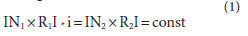
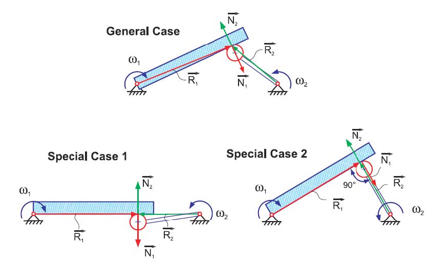
Figure 2 Line of constant vector products.
- Click image to enlarge
The material elements
of the belt, when shifted along the connecting
straight line, result in a constant
transmission ratio between disk 1 and
disk 2. If one imagines finite surface elements
whose normal direction in any
case are consistent with the direction of
the connecting line, then the requirements
for a constant transmission ratio
are fulfilled. The vector product only
yields the perpendicular portions of the
two multiplied vectors, which is why the
solution for Equation 1 is given for any
point along the connecting line as:

where:
Rb1 radius magnitude of base circle 1
Rb2 radius magnitude of base circle 2
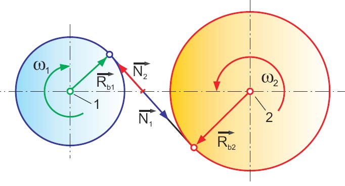
If the finite surface elements are connected
with the respective disk, then
based on disk 1 in Figure 3, the rotation
of the surface element “a” around Axis 1
about the angular increment between Ra
and Rb rotates the green element “a” up,
in the position at the arrow tip of Rb. This
equals the rotation required in order to
move from contacting point “a” to contacting
point “b” along the connecting
line (Fig. 2). The connecting line (Fig. 1.)
2 becomes the line of engagement in
Figure 3.

Figure 3 Surface elements that fulfill constant vector products.
- Click image to enlarge
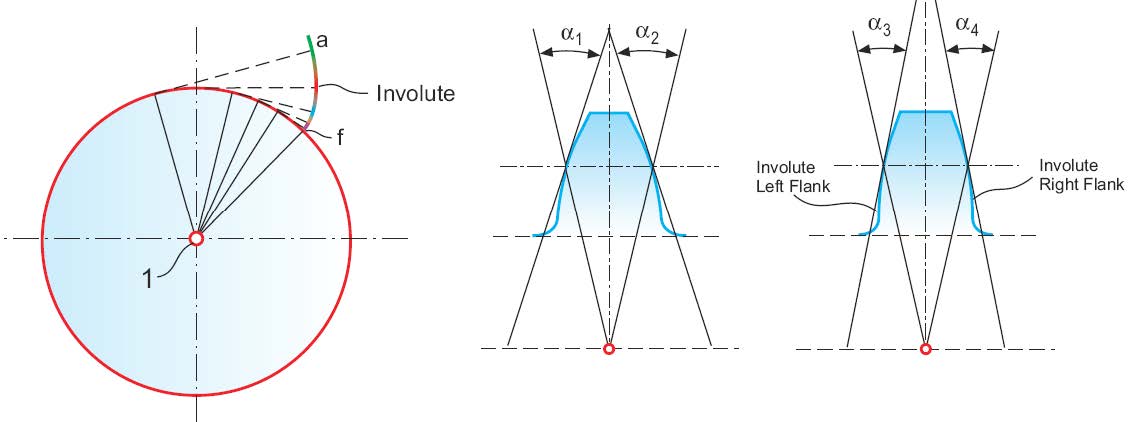
If the explained construction
is applied to the surface elements “a” through “f,” then a flank form with variable
curvature — as shown above position
“f ” — is the result. Studying the construction
of the resulting flank form in Figure
3 shows the analogy to the involute construction
with a cord. The cord in this
case is wound around the base circle and
then gets unwound, with its end under
tension, from position “f“ to position “a.”

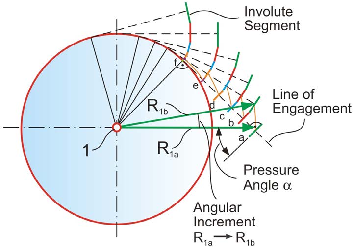
Figure 4 Continuum of connecting points.
- Click image to enlarge
The dashed lines in Figure 4 symbolize
the cord in discrete, unwound positions.
The end of the unwound cord traces a
curve — i.e., flank form — which mathematically
represents an involute. The
right part of Figure 4 demonstrates the
tooth form in case of a standard pressure
angle (α1,2) and in case of a small pressure
angle (α3,4), assembled from a left and
right flank. Both tooth forms (pressure
angles) can be generated from the same
involute (Fig. 4, left) by choosing the section
of the tooth depth (height) closer to
the base circle (small pressure angle) or
radially farther away from the base circle.
If the pitch diameter should remain constant
during a pressure angle change, it is,
for example, possible to reduce the base
circle diameter in order to increase the
pressure angle.
The requirement to keep the crossproduct
for each of the transmission elements
independent from one another and
constant, as well as the idea of employing
the functionality of a crossed belt
drive as an example for the movements
of finite surface elements, led without
any mathematical derivations or analysis
to an interesting solution. The involute
has a number of remarkable properties
(in contrast to other flank forms), like
its manufacturability via a simple trap-ezoidal rack profile and its insensitivity
to center distance changes between two
engaged gears.
A continuous transmission of rotation
between two axes is not possible with
only a single involute on the circumference
of each of two engaged disks. A continuous
transmission requires the continuation
of the rotational transmission process
by the discrete pair of involutes on
several positions along the circumference
of each disk. The repetition of the flank
structure is illustrated in Figure 5. The
angular distance of the teeth along the
circumference of a disk is called “pitch”
or “circular pitch.” Using the relationship
between module and pitch in Equation
6 assures sufficient overlap during the
change of transmission contact from one
pair of teeth to the next. In order to allow
transmission in both rotational directions
it is necessary to develop an opposite
involute as a mirror image of the
first developed involute. The opposite
involute can be developed using a line of
engagement which corresponds to the
second part of the crossed belt. The angular
distance between the two involutes of
one tooth is normally defined as half-apitch
reduced by half-the-amount of the
desired backlash.

where:
PW angular pitch
PB circular pitch
d0 pitch diameter
z number of teeth
The module is introduced in order to
standardize the tooth proportions; Figure
5 includes the most important tooth proportions.

Figure 5 Tooth proportions.
- Click image to enlarge
Common values for the tooth proportions
are:

where:
m module
hK addendum
hF dedendum
H whole depth
The addendum is larger than the
dedendum to assure that the tops of the
mating gear teeth can pass the root area
without interference. In addition, the
extra space in the root area is used for a
root fillet radius as a transition between
the involute flank and root bottom.
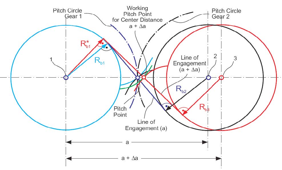
Involutes and Center Distances
The interaction between two involutes
is schematically shown (Fig. 6).
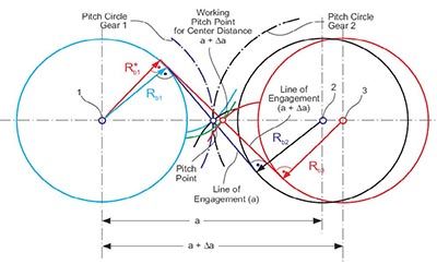
Figure 6 Center distance insensitivity of involute gearing.
- Click image to enlarge
The
pitch circles divide the center distance
into the two operating radii for transmission
of the rotation. The connecting
line between the two axes intersects
with the line of engagement at the tangential
contacting point of the two pitch
circles (pitch point). If the two meshing
involutes are rotated until their contacting
point matches the pitch point,
then a condition of rolling without sliding
exists. A further rotation to contacting
points — above or below the center
distance connection line — changes the
pure rolling to a combination of rolling
and sliding (general mesh condition).
The angle between the center distance
connection and a line perpendicular to
the line of engagement is called the pressure
angle (Fig. 3). A shifting of gear “2”
with its center into position “3” (a + Δa)
results in a new line of engagement. With
a small rotation of the two gears 1 and 3
the contacting point can be moved to lie
again on the center distance connection.
This point is called the “working pitch
point” because here only rolling without
sliding occurs. The working pitch
point divides the center distance (just like
the pitch point before) according to the
transmission ratio. A rotation of gear 1
in clockwise direction shifts the contact
point along the line of engagement (like
in case of the original center distance “a”)
where the surface normals of the flank
contacting point will match the direction
of the new line of engagement. Therefore,
the absolute amount of the vector product
between the normal vectors and the
radius vectors will also here equal the
magnitude of the base circle radii. This
in turn causes the ratio between gear 1
and gear 2 to be identical to that between
gear 1 and gear 3. This particular effect is
called the “center distance insensitivity of
involute gearing.”
Generating the Involute
A generating rack as shown (bottom,
Fig. 7) has cutting edges that are oriented
perpendicular to the line of engagement.
One edge of the trapezoidal profile (Fig. 7)
is drawn to match the pitch point.
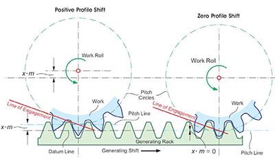
Figure 7 Involute development with straight generating rack.
- Click image to enlarge
A horizontal
shifting of the generating rack to
the right creates at the right side of the
observed center tooth the addendum profile
(or the lower part of the involute in
Figure 7); and on the left side of the same
tooth the dedendum profile. The gear is
rotated counter-clockwise during this generating
rack shift as if the pitch circle of
the gear would roll on the pitch line of
the generating rack without any sliding.
The straight cutting edge profile will be
perpendicular to the line of engagement
in any shift position — which is why this
arrangement fulfills the requirements of
the involute forming process — as shown
with the cord construction.
The right part of Figure 7 explains
how a work gear shift away from the rack with an amount of × * m leads to a shorter
involute between the pitch line and the
root and to an extended involute between
the pitch line and the tip of the tooth (a
different section of the same involute is
used). As result, a stubby tooth with larger
tooth root thickness and reduced tip
thickness is generated. The tendency of
a so-called “undercut” condition (compare
Figure 7, left and right) is eliminated
due to this work gear shift. The work gear
shift is called “profile shift” (or addendum
modification).
If the gear with profile shift is mated
with a “zero profile shift gear,” then
the pair has a center distance, which is
enlarged by the amount of the profile
shift. In order to re-establish the theoretical
center distance, the mating gear can
be manufactured with the same amount
of profile shift — but with a negative sign.
Such a gearset is called a “V0 pair;” it can
be exchanged in an existing gearbox with
a non-profile shifted set. V0 pairs keep
their pitch circles as operating roll circles.
In the case of varying profile shifted
pairs — in addition to the change in center
distance — a change in the operating
roll circle and a change in the operating
pressure angle is observed. Every combination
between varying profile shifted
gears is possible and has no influence on
the transmission ratio; i.e. — the constant
transmission of rotation (Refs. 2–3).
This manufacturing principle via
toothed rack exists in practical form as a
planing method (Fig. 8, left). A reciprocating
planing rack — which performs a
combination of cutting and withdrawn
reverse stroke — is shifted sideways while
the work gear rotates a predetermined
amount in order to generate the involute
profile.
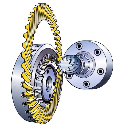
For soft cutting, “threaded” hobs
(Fig. 8, right) are mostly used. The discrete
cutting blades are grouped along a
helix on the surface of a cylinder.

Figure 8 Manufacturing of involute tooth forms.
- Click image to enlarge
Hobs
are swiveled to an angular position in
order to compensate for the helix lead
angle. During the continuous hob rotation,
a feed motion moves the hob along
the face width of the work gear (“E” in
Fig. 8). In case of a single start hob, the
work gear will rotate one tooth (one
pitch) during one hob rotation. A number
of other methods for the manufacture
of involute gears are also derived from
the generating principle with a trapezoidal
rack.
The so called profile cutting or grinding
methods are based on cutting or
grinding tools whose tooth forming profile
sections represent a negative “involute.”
Profile tools are more difficult
to manufacture than generating tools,
and are more sensitive to positioning
errors and process related kinematic,
i.e. — dynamic influences.
The Conclusion from the
Cylindrical Gear to the Bevel Gear
It is possible to apply the conclusions
of the preceding sections in a similar
form also to three-dimensional gearing
applications. If motion and force should
be transmitted between two non-parallel
axes, the solution beyond to worm
gear drives and crossed helical gear
drives is the most remarkable case in
gearing — bevel gears. These are angular
transmissions with conical gears that
have straight or curved teeth in direction
of the face width. Depending on the
axes orientation, bevel gears are divided
in straight or spiral bevel gears with
intersecting axes, and hypoid gears with
crossing axes which are separated by an
offset. The different bevel gear types are
explained in Chapter 3 in detail with
their properties and applications.
The conclusion from “N to N + 1” from
the cylindrical gear to the bevel gear can
be created intuitively if the generating rack
(Fig. 8) is placed on a flat surface and then
bent around a vertical axis (Fig. 9). If the
rack is imagined to consist of thin, elastic
material, then only the cylindrical section
through the middle of the face width
of the toothed ring (Fig. 9) shows the
original trapezoidal rack profile (Fig. 8),
i.e. — rolled on the surface of said cylinder.
The trapezoidal profile reduces in size
proportionally towards the center and
enlarges proportionally towards the outside.
If this proportional profile distortion
does not only apply in circumferential
direction but also in vertical direction,
then the optimal generating gear
for straight bevel gears has been created.
This leads to a simple explanation of the
generating principle in Figure 9. If a disk
from modeling clay is pressed from the
top into the profile of the generating gear
and a slip free rotation between disk and
generating gear occurs, then teeth with
nearly involute profiles are formed. The
profiles formed in this experiment are
spherical involutes, or octoids of the first
kind. If the same experiment is repeated
with a disk from modeling clay from the
lower side of the generating gear, then a
second bevel gear with an octoid profile
is created. Remarkably enough, in the
conducted brain experiment the most
elementary case of the kinematic coupling
requirements between two gears
has been realized. If it is possible for the upper bevel gear to engage in a perfect
meshing condition with the generating
gear — and if the lower bevel gear can
engage in a perfect meshing condition
with the mirror-imaged bottom side of
the generating gear — then the generating
gear (which has only a virtual character)
can be removed and the two bevel gears
will mesh perfectly with each other as
well. This leads to the formal definition
of the kinematic coupling requirements.
Kinematic Coupling Requirements
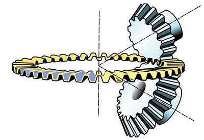
Figure 9 Generating principle of straight bevel gears.
- Click image to enlarge
- The flank surfaces of the generating
gears of the two mating bevel gears
are congruent (same shape but mirror
images (Fig. 9))
- The generating gears of the two mating
bevel gears require identical axes of
rotation (top/bottom sides of generating
gear in Figure 9 form the same generating
gear which rotates in both cases
around the same axis and therefore satisfies
condition 2)
- The surface of engagement of pinion
and ring gear must be identical to the
surface of engagement between pinion
and generating gear, and also to the one
between ring gear and generating gear
(without detailed knowledge of the surfaces
of engagement, the global condition
in Figure 9 seems to satisfy this
requirement)
With all coupling requirements satisfied,
the ring gear flanks are conjugate to
the pinion flanks. (The term conjugate
is used in mathematics for two or more
surfaces which contact each other along
a line. Since the 1980s the term conjugate
is also employed in the gear technology
literature to define the “exact” gear pair
which presents a triple plurality of line
contact between two gear flanks during
the meshing process (Ref. 4). This book
will apply this application of the term
conjugate according to the following definition,
since it is commonly used today.
Definition of the Conjugate Gear
Pair
- The flanks contact along a line (contact
line), which is only limited by the
boundaries of the teeth, i.e. — the overlapped
area
- The line contact between the flanks
exists within the entire area of engagement
in every mesh position
- Line contact is maintained in the entire
area of engagement even if pinion and
ring gear are rotated by angular increments
as long as those increments
exactly fulfill the transmission ratio
A functional and conjugate bevel
gear set can be generated even if not all
requirements from above are fulfilled.
This will require the implementation of
certain corrections. However, the robustness
and stability of a certain design will
be diminished when fewer of the kinematic
coupling requirements are satisfied.
The violation of a coupling requirement
and the resulting consequences to the
functionality are not connected like binary
conditions. An increasing deviation
from a single requirement results in an
increased limitation in the roll and transmission
quality of a gearset.
When the involute flank generation
of cylindrical gears was applied to bevel
gears in Figure 9, the trapezoidal gener-ating profile with plain “side walls” was
used as the basis for the plain generating
gear for straight bevel gears. The generating
principle of conjugate flank pairs
between pinion and ring gear works for a
wide variety of flank length forms as long
as certain rules are respected.
It is, for example, possible to expand
the function of the straight tooth plain
generating gear of Figure 9 to a plain
generating gear with curved teeth and
subsequently arrive at Figure 10. At the
left side of the generating gear (Fig. 10),
a cutter head is shown that has blades
that are oriented a certain distance from
the cutter head center, which represent
one tooth of the generating gear. This
arrangement allows for a continuous
rotation of the cutter head that results
in an efficient chip removal in the tooth
slots. The teeth of the resulting spiral
bevel gear are oriented under an angle
to the radial orientation of the straight
bevel gear teeth (Fig. 9). A radial section
(with an axial plane) will cut through two
or even more teeth. This means for the
pinions and gears manufactured with the
generating gear in Figure 10, that more
than one pair of teeth is in mesh and
participates in the transmission at any
time. This effect, called the “modified
contact ratio,” results in larger transmittable
torques and a smoother rolling of
the flanks.

Figure 10 Generating principle of spiral bevel gears.
- Click image to enlarge
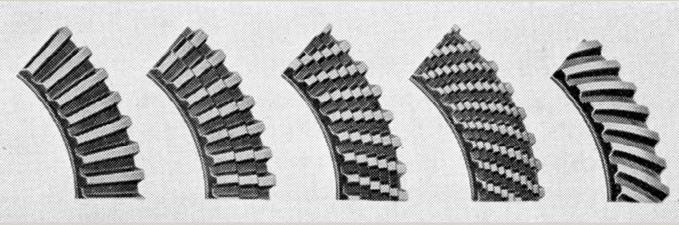
An intuitive justification of the step
from straight teeth to curved teeth is
demonstrated in Figure 11.

- Click image to enlarge
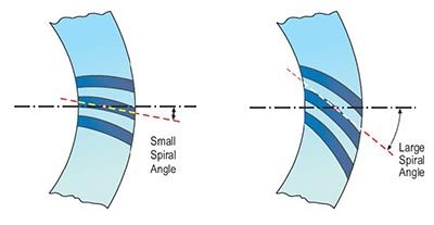
Figure 11 Model for creation of curved teeth and explanation of spiral angle.
- Click image to enlarge
The straight
teeth to the left (Fig.11, top) are divided
into more and more segments; the segments
are then rotated along the face
width from left to right. An infinite number
of segments with infinitesimally small
rotations deliver eventually the spiral
bevel teeth (right, Fig. 11, top). The definition
of the spiral angle is demonstrated
in the lower part of the same figure (the
drawing plane is equal to the generating
plane). The rules regarding the shape
of the flank line curves (and pressure
angle) that have to be followed in order to
assure undisturbed meshing will be summarized
in the second half of this chapter,
which will appear in the next issue
of Gear Technology. The second half also
delves into more detail with regard to
the different methods of generating bevel
gear teeth.
Summary
- At the beginning of this chapter some
thoughts about plausible explanations
of the gearing law were discussed.
- Involute gearing was then presented
as the consequential result of the engineering
demand for a robustly functioning,
easy-to-manufacture tooth
form.
References
- Buckingham, E. Spur Gears, McGraw-Hill Book
Company, Inc., New York and London 1928.
- Niemann, G. and H. Winter. Maschinenelemente
I, II & III, Springer-Verlag Berlin, Heidelberg,
New York, Tokyo, 1983.
- Dudley, D. Dudley’s Gear Handbook, McGraw-
Hill, Inc. New York 1991.
- Schriefer, H. “Verzahnungsgeometrie
und Laufverhalten bogenverzahnter
Kegelradgetriebe,” Dissertation, RWTH Aachen,
1983.
- Stadtfeld, H.J. “Anforderungsgerechte
Auslegung bogenverzahnter Kegel-Radgetriebe,”
Dissertation, RWTH Aachen, 1987.
- Brandner, G. “Kreisbogenverzahnte Kegelräder,”
Maschinenbautechnik, 3. Jg. Issue 5 May 1954.
- Richter, E.H. “Geometrische Grundlagen der
Kreisbogenverzahnung und ihre Herstellung,”
Konstruktion, Issue 3, 1958.
Gleason Bevel Gear Technology can be
purchased ($68; 50% student discount) via the
Gleason Website by clicking “About Gleason”
– followed by “Gleason Company Store” – and
then “Promotional Items.”
About Author
Dr. Hermann J.
Stadtfeld received in
1978 his B.S. and in 1982 his
M.S. degrees in mechanical
engineering at the Technical
University in Aachen,
Germany; upon receiving
his Doctorate, he remained
as a research scientist at the University’s
Machine Tool Laboratory. In 1987, he accepted
the position of head of engineering and R&D
of the Bevel Gear Machine Tool Division of
Oerlikon Buehrle AG in Zurich and, in 1992,
returned to academia as visiting professor
at the Rochester Institute of Technology.
Dr. Stadtfeld returned to the commercial
workplace in 1994 — joining The Gleason
Works — also in Rochester — first as director
of R&D, and, in 1996, as vice president R&D.
During a three-year hiatus (2002-2005) from
Gleason, he established a gear research
company in Germany while simultaneously
accepting a professorship to teach gear
technology courses at the University of
Ilmenau. Stadtfeld subsequently returned to
the Gleason Corporation in 2005, where he
currently holds the position of vice president,
bevel gear technology and R&D. A prolific
author (and frequent contributor to Gear
Technology), Dr. Stadtfeld has published more
than 200 technical papers and 10 books on
bevel gear technology; he also controls more
than 50 international patents on gear design,
gear process, tools and machinery.