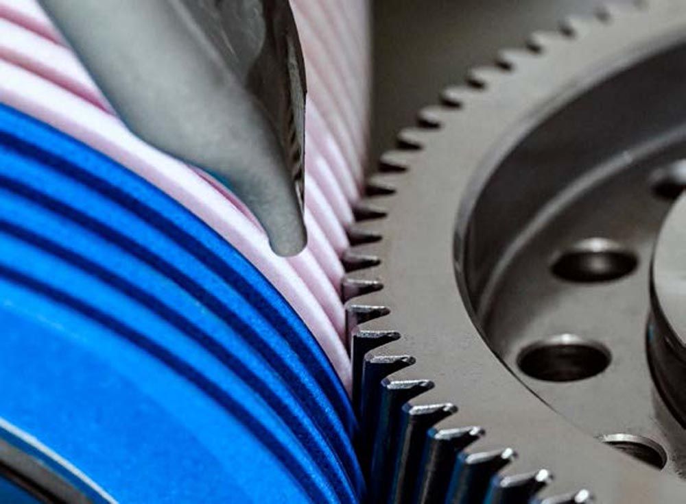
This article introduces the process of polish grinding of gears. Improved surface quality increases the overall efficiency of gearboxes, resulting in reduced friction and torque loss, higher power density, and noise-optimized gears (lower NVH); all these factors are highly relevant, especially for electric drives. When Reishauer developed polish grinding in 2012, the process aimed to improve the efficiency of ICE engine transmissions, and the set goals were easy to achieve. Today, in 2023, the situation is dramatically different. While an ICE engine operates at around 3,000 rpm and supplies acoustic masking of the gear noise, EV drivetrains feature up to 20,000 rpm and offer no such masking.
For this reason, EV gears must run substantially quieter. Furthermore, both left and gear flanks must perform identically for acceleration and deceleration due to regenerative braking. When looking at the surface texture, we must distinguish between roughness, waviness, and form. Any of these parameters can influence the performance of a gear. Polish grinding can only influence the roughness, not waviness or form. The grinding process must control form errors and waviness before polishing takes place. However, the continuous generating gear grinding process has proven to supply excellent quality in form, waviness, and pitch. Continuous generating gear grinding delivers a surface roughness of around Ra 0.3 µm, which has to be reduced by a subsequent polish grinding stroke. Let’s take a moment to ponder the term surface roughness:
“It’s common to hear ‘surface roughness’ described as a number that can be measured by a gauge. But describing surface texture with a number is a lot like describing a concert in decibels: Loudness is just part of the story. A rock band, an orchestra, and a chainsaw can all produce 100 decibels, but the full picture is much more complex and interesting.” (Ref. 1)
The Process
The basic technology for polishing grinding is continuous generating grinding. Based on a dressable grinding worm, this method has proven itself in terms of flexibility and high productivity. The kinematics of this process can be understood as a worm drive with rotational movements of the grinding worm and the workpiece (nB and nc), see Figure 2, with additional abrasive machining movements consisting of an infeed X, vertical feed Z, and lateral shift movement Y. The interaction of parameters creates a “contact zone.” The contact zone comprises a contact length lk, contact width ap, and contact depth ae.
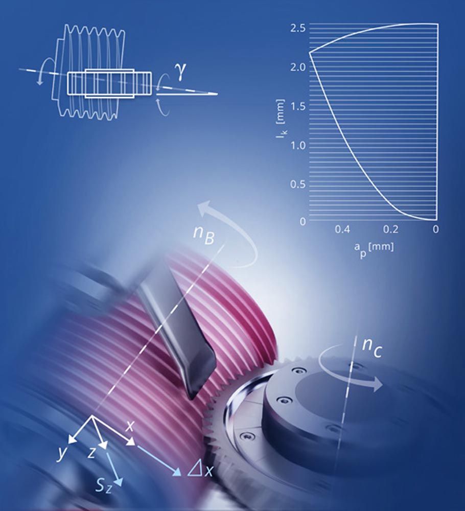
Figure 2—Principle of continuous generating grinding.
Polish grinding is performed as a final machining sequence, with the workpiece remaining clamped on the same workpiece carrier during both grinding and polish grinding. Also, most importantly, polish grinding does not aim to impart the surface with a mirror finish. First and foremost, polish grinding must produce a functional surface, a surface that features reduced friction while still capable of retaining an oil film during gear meshing.
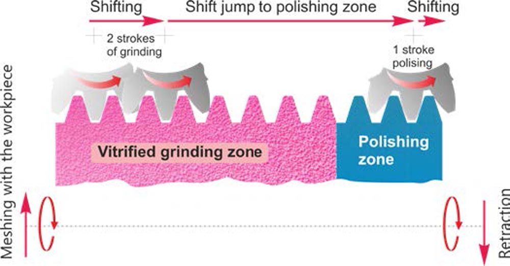
Polish grinding follows immediately after conventional generating grinding, typically consisting of a rough and finish grinding pass. For this purpose, the grinding worm is divided into the grinding and polishing zones.
This final sequence is a polish grinding pass using the elastic, resin-bonded section of the grinding worm. There are some fundamental differences between grinding and polish grinding. Simply put, grinding uses larger grain sizes and more rigid bond structures. For grinding, a grain size of 80 is used, with an average grain diameter of 185 µm. For polish grinding, a grain size of 800 is used, with an average grain diameter of 7 µm. When polish grinding ICE gears, the selection and combination of grinding and polishing zone was easy as most combinations worked immediately. However, combining the right grinding wheel and polish wheel section for EV gears requires much experience. For example, using the same polishing section but two different grinding sections results in very different polished surfaces. The right grinding section must be selected initially for the polish wheel to deliver the right final surface requirements.
Grinding aims to achieve perfect geometry, a “good” surface quality, gear flanks free of waviness, form accuracy, and high material removal rates. As a subsequent step to grinding, polish grinding should not alter the geometry created by grinding. However, it increases the load-bearing capacity of the tooth flanks by removing surface peaks. Moreover, for technical purposes, polish grinding should only remove the peaks of surface roughness and leave the roughness of the surface valleys intact so that an oil film can adhere to the polished surface. The increase in the load-bearing portion of the gear tooth flanks allows gear designers to boost the power density of the gearboxes.
After the roughing and finishing grinding passes, the grinding worm shifts via a jump from the vitrified bonded zone to the polishing zone for the final machining pass, as shown in Figure 3.
Figure 3—Principle of continuous generating polishing grinding.
Using a combined grinding and polishing wheel offers a significant advantage over alternative methods, such as vibratory finishing, which requires a prior grinding process and, thus, two different machine tools and more complex material handling. Continuous generating grinding requires only one machine tool. It grinds and polishes the component in one clamping, making it economically viable for mass production. In the combined process, polish grinding perfectly follows the gear profile and flank line’s precision-ground micro and macro geometries.
Scientific Basis
A research project by NASA’s research center confirmed as early as 2002 that superfinish-ground (polished) gears have a fourfold lifespan compared to conventionally ground gears (Ref. 2). In this case, the polishing finish was achieved by immersing the gear parts in an abrasive medium and subjecting them to vibratory finishing. Polished surfaces increase the service life of gears as they reduce micro-pitting and lead to lower friction in the gear meshing process and, hence, higher transmission efficiency.
Surface Characterization
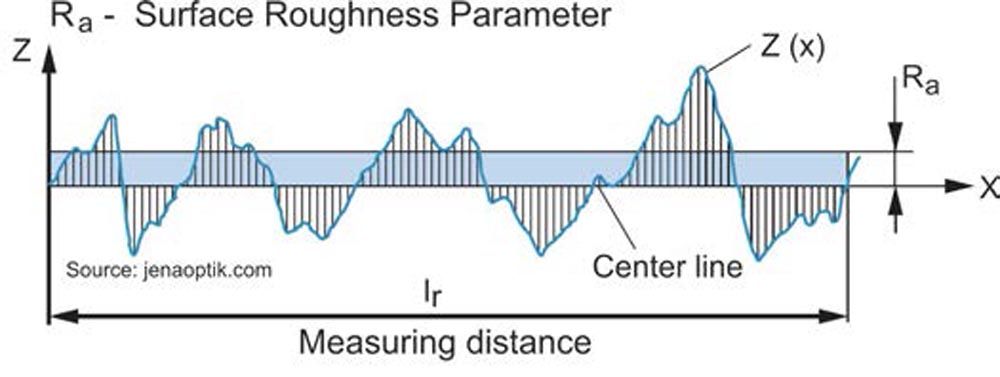
One such number would be Ra, the arithmetic average of the profile height deviations from the mean line, the most common value for describing ground surfaces. However, this is mostly for historical reasons, as early roughness gauges were limited to this particular parameter. However, Ra is not very useful for polish grinding as the same Ra value can have various surface characteristics. The problem of why Ra is not useful for polish grinding is given by its definition: The average deviations from the mean line. In other words, the average is taken from the valleys’ depth and peaks’ heights along a defined distance. According to this definition, two very different surfaces could be identical: one with high and low valleys and the other with low and deep valleys. Furthermore, Ra does not differentiate between narrow and wide spacing between peaks and valleys, although the spacing may significantly influence gear noise generation. Hence, while different measured surfaces may have identical Ra values, the resulting performance of meshing gear flanks, although of identical Ra values, may be worlds apart regarding gear noise and vibrations.
Figure 4—Ra surface roughness parameter.
As M. Stewart writes in an SME paper from 1990:
“Tribology studies have shown that the ideal sliding surface is smooth with relatively deep valleys to hold and distribute the lubricant. However, quantifying and specifying these surfaces has always been a problem. Since its introduction, the bearing area curve - the Abbott curve - has been recognized as the only effective method for characterizing these surfaces but is rarely used in specifications.” (Ref. 3)
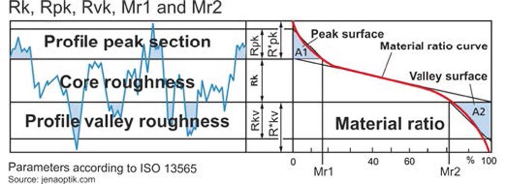
The Abbott curve, Figure 5, is a much better indicator for predicting the load-bearing wear behavior of gear flanks than the roughness value Ra. The arithmetic mean deviation Ra does not differentiate between peaks and valleys and, therefore, has a relatively weak informational character. Furthermore, it should be highlighted here that, to date, there are no common standards for polishing grinding, and users have different ideas concerning the polishing characteristics they aim for. Thus, an identical Ra value can describe a surface with high peaks and shallow valleys or a surface with low peaks and deep valleys. For this reason, users today prefer the Rvk value, which describes the reduced groove depth. This parameter is used to characterize valleys that retain lubricant. During the polishing process, the Rpk value (the peaks) is altered more than the Rvk value (the valleys). The goal of polish grinding should be to reduce the Rpk and leave the Rvk as much as possible intact, with the further goal that the Rpk value remains identical on both flanks.
While one must be careful to declare absolute surface characterization values for polish grinding, the following values may serve as a guideline:
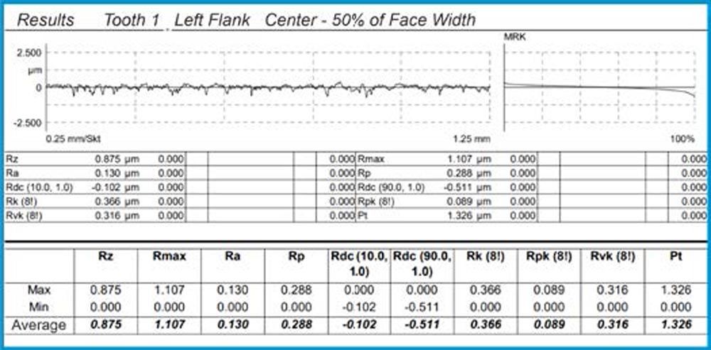
Rpk 0.15 µm, Rk 0.4 µm, Rvk 0.25 µm, Ra 0.1 µm
Figure 5—Abbott material ratio curve.
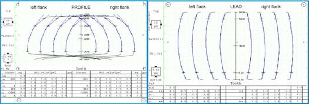
Figures 6 and 7 show the typical results of polish grinding, profile, lead, and surface roughness on a typical automotive ring gear.
Figure 6—Profile and lead measuring chart of ring gear, module 2.4.
Figure 7—Surface roughness measurement of ring gear, module 2.4.
Economic Considerations and Conclusion
The direct integration of polish grinding as a subsequent step in the conventional generating grinding process results in minimal investment costs if customers already have Reishauer generating grinding machines. Moreover, the diamond dressing tools remain the same as with conventional methods. Polish grinding also requires only minimal additional operator training. Although the cycle time increases slightly due to the additional polishing stroke, this is offset by the gain in product quality.
Additional costs arise from purchasing special grinding wheels with two different areas for grinding and polishing. The higher process costs compared to conventional gear grinding are more than offset by the benefits of reduced torque loss, higher load-bearing capacity of polished ground gears, and higher power density in the gearboxes.
References