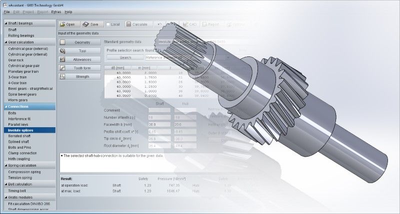
Calculation of Involute Spline Extended
GWJ offers an extensive calculation module for involute splines within its market-leading web-based calculation solution eAssistant. The eAssistant—the engineering Assistant—has already been used successfully worldwide for 20 years. The module for involute splines is suitable for both new designs and recalculation or reengineering and offers simple and fast calculation of both the main geometries and the exact tooth form including inspection dimensions and tolerances as well as strength of involute splines.
In addition to the calculation of splines according to DIN 5480, connections according to ISO 4156, ANSI B92.1 (inch version), and ANSI B92.2 (metric versions) are also supported. Furthermore, the calculation of spline profiles according to DIN 5482 is also possible. Although this standard can no longer be used for new designs, it is still used or in demand for spare parts due to its widespread use.
The French standard NF E 22-141 from 1955 has been added to the eAssistant calculation module for involute splines. In the module, the Primary Series is available as the recommended preferred series of NF E 22-141 for flank-centered splines with a flat tooth root. In addition to the involute splines profiles, the corresponding tool rack profiles can be selected. Here the user can choose the tool profile for hobbing and for hubs the tool profiles for broaching and shaping.
The gear tooth qualities between 5 and 12 as well as the tolerance series of NF E 22-141 for the calculation of the test dimensions, such as tooth space allowances via the number of measuring teeth or diametrical roller or ball dimension, can also be selected from the list boxes. The tolerance series c10 and f10 for sliding fits, js10 for interference fits, and x10 for force fits are available.
By using the eAssistant plugins, the splines and the hubs can be generated as 3D models directly in the respective CAD system and the table with the manufacturing data can be placed on the drawing.
As an alternative to the CAD plugins, the output of the tooth form is also available in 2D DXF format or 3D STEP/IGES. In this way, the exactly calculated tooth form for the correspondingly selected tolerance position can also be used, for example, for laser cutting or wire eroding.


