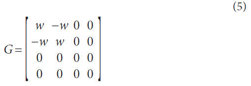
Synchronization property. When the oscillator is subjected
to an external periodic signal p (Ωt), the mathematical model of
Matsuoka’s neural oscillator becomes:

Where, ED is an input matrix as follows:
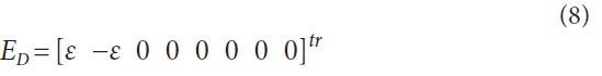
Here, ε is an input gain, and p (Ωt) is a normalized sinusoidal
signal whose frequency is Ω. If the frequency Ω is partially close
to the Eigen frequency ωD of the neural oscillator, the oscillator
is thus synchronized with the external sinusoidal wave.
This synchronization phenomenon can be seen when the
detuning Ω-ωD between the oscillator’s frequency ωD and the
external periodic force’s frequency Ω is a finite value. According
to an analysis by the phase reduction method (Refs. 9–10), the
synchronization region ε Γmin < Ω-ωD < ε Γmax is decided. Here,
Γmin, max is the phase coupling function of the oscillator.
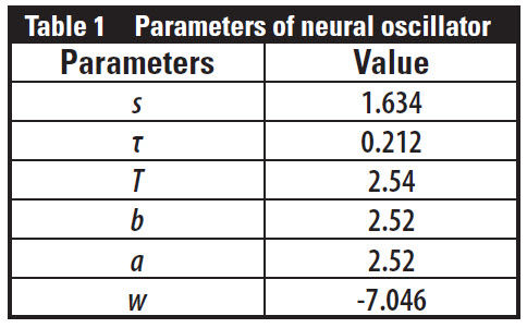
Figure 1 shows a synchronization region of the neural oscillator
(Table 1).
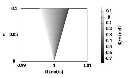
Figure 1 Synchronizing region of neural oscillator.
The colored area is the region also known as
Arnold’s tongue. In this figure the horizontal axis is the frequency
Ω of input, and the vertical axis is the amplitude ε of
input. It is clear that the synchronization region has spread
from the oscillator’s frequency ωD = 1 — when the amplitude of
the external forcing is increased. The synchronization region
depends on the amplitude
of the forcing.
Increased the coefficient
for the external
forcing in the neural
oscillator, the region
can be freely adjusted.
The color in this figure
shows the phase difference (phase locking points) between input/output of the
neural oscillator.
While the neural oscillator has a sensitive reaction to the sinusoidal
input within the synchronization region, it does not have
the same sensitivity to the input outside of the region. Thus the
neural oscillator can be used as an adaptive, single-frequency
generator, and as an adaptive notch filter to cancel the unnecessary
frequency component in the vibration response of the
meshing gears.
Gear Meshing
In this section a model of gear meshing vibration in a circumferential
direction — used for verification of a proposed noise-can-cellation system by simulation — is explained. Later, amplitude
and frequency modulation caused by the eccentricities of gears
are considered.
Dynamic loads on gear teeth. A simple vibration model in
meshing gear pairs is used for simulation (Fig. 2).
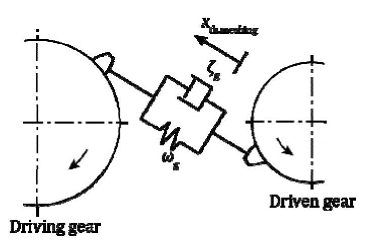
Figure 2 Vibration model in meshing gear pairs.
Each gear has
a mass and is connected to the other by a spring and damper
(Ref. 11). This vibration model — in a circumferential direction
— is considered to be a single-degree-of-freedom vibration
system as follows:

Where, xth, meshing (t) is spring deflection of the vibration system;
ωg is the natural frequency of the system; ζg is the damping
ratio depending on the gear material; e(t) is tooth profile
error — and this error is the input displacement to the system.
Here it was assumed that the driving torque variation of the
rotating shaft was small and the effect of the shaft stiffness on
the line of action of force was small as well.
A meshing condition of a spur gear pair varies with time t.
Considering the meshing period Tz, periodic change of total
tooth stiffness during 0 ≤ t < z2Tz is expressed as follows:

In this study, the tooth profile error e(t) is also expressed as
follows:
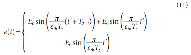
Where, εth is contact ratio of the spur gear pair, and is
obtained as follows:
ωg,j is the time-varying, natural frequency of the meshing gear
system during meshing period that is derived from Ishikawa’s
tooth stiffness variation and the equivalent inertia mass on the
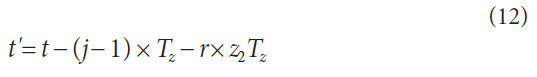
pitch circle (Ref. 12). In addition, subscript j indicates the number
of meshing tooth pairs, obtained as follows:

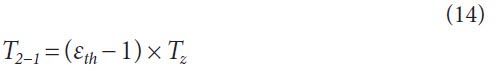
By using contact ratio εth,the transition time T2-1 from two
pair teeth in mesh to a single pair is obtained as follows:
And Tsmooth is a time constant of a first-order lag system to
vary the natural frequency smoothly, here as Tsmooth = σsmoothTz.
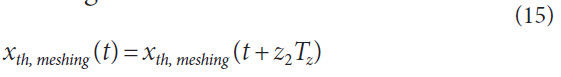
Xth,meshing changes periodically, the timeframe dependent upon
the rotation of the driven gear as follows:
Amplitude and frequency modulation by an eccentric error
of a driven gear. Generally the vibration caused by the tooth-totooth
meshing of a rotating gear pair contains various frequency
components that are due not only to amplitude and frequency
modulation caused by eccentricity of gears, but also to the rolling-
elements noise of bearings, motor vibration and its harmonics,
and so on. The effects of these unnecessary components on
the measured vibration make detection of gear faults — such as
gear tooth cracks — difficult.
In this subsection a model that includes the amplitude and frequency
modulation caused by an eccentric error of a driven gear
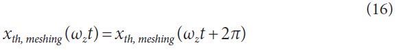
is considered. Considering the meshing frequency ωz = 2π/Tz, the
periodic variable is expressed as follows:
The effect of amplitude and frequency modulation on the
variable can be expressed as follows
(Ref. 13):

Where,
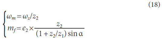
and e2 is the ratio of the radius of pitch circle of the driven gear
to the eccentric error of the gear; ka is the amplitude modulation
factor; mf is the frequency modulation factor; α is the pressure
angle; and z the tooth number.
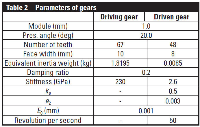
Numerical simulation of meshing gear vibration. According
to the abovementioned gear model, numerical simulations of meshing gears are carried out using the Runge-Kutta Fourth
Order Method (Table 2). The step time of the simulations is
10-6 s, and σsmooth = 10-2.
The results of numerical simulations are shown in following
figures. Figure 3 shows the change of the natural frequency of
the system.
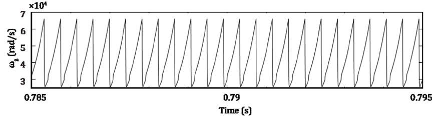
Figure 3 Natural frequency of gear meshing.
In this figure the natural frequency changed periodically
because the meshing condition of a spur gear pair varied
with time t. In considering the change of the natural frequency,
the acceleration response of the system is obtained (Fig. 4).
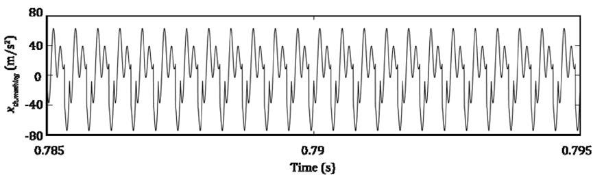
Figure 4 Acceleration response of gear meshing.
As for the eccentric error of the gear, the acceleration response
of the system is subject to influence by both amplitude and
frequency modulation (Fig. 5).
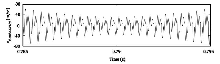
Figure 5 Acceleration response of gear meshing with AM and FM.
Figures 6 and 7 show the frequency
responses, with and without modulation, respectively.
As a result of the modulation some sideband peaks can be seen
(Fig. 7) when compared with Figure 6.
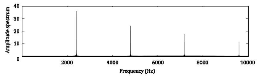
Figure 6 FFT of gear meshing.
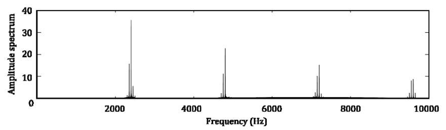
Figure 7 FFT of gear meshing with AM and FM.
Noise-Canceling System
Here a noise cancellation system using neural oscillators to filter
out the background noise of vibration in meshing plastic
gear pairs for detection of failure signs of the gears is explained.
The acceleration response, which is measured on the top of the
housing at the gear shaft bearing, includes not only the DC;
shaft frequency; its harmonics; fundamental meshing frequency;
some mesh harmonics; and its modulating sidebands; but
also rolling-elements noise of bearings, motor vibration and its
harmonics, and so on. Detecting gear faults is much more difficult
in the complex response; therefore these unnecessary frequency
components should be eliminated from the response.
However, the frequency of the unnecessary components
attracts a great amount of influence from the driving torque variation.
The proposed new filter system using the neural oscillators
can autonomously follow the frequency change of the unnecessary
component due to the synchronization property (Fig. 8).
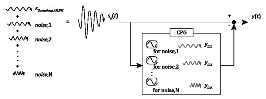
Figure 8 Concept of feed-forward noise cancelling system using neural oscillators.
The proposed system has a measured signal and consists of
some neural oscillators. The number of oscillators is the same as
the number of unnecessary components. Each neural oscillator
is designed to tune the natural frequency in to a particular frequency
of the component. Moreover, the output of the oscillators
is set to be out-of-phase with the input by 180° and is combined
with the original, measured response to reduce the amplitude of
the unnecessary components. The system is expressed as follows:
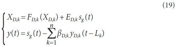
where βDk is an arbitrary output gain of the oscillator, and Lk
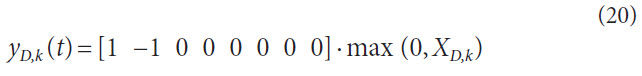
is a delay time of the system. Moreover, the output of the each
oscillator is obtained as follows:
Results of Numerical Simulation
to the simulated response to confirm validity of the system. In
this simulation the analyzed signal consists of the abovementioned
acceleration response and an unnecessary component
20sin (2π *7,250*t), which is the same frequency of the modulated,
third-order, high-frequency content.
Figure 9 shows the abovementioned acceleration response
without the noise, and Figure 10 the signal with the noise; in
both figures the time is multiplied by 2π *7,250.
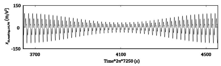
Figure 9 Acceleration response of gear meshing with AM and FM.
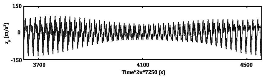
Figure 10 Acceleration response of gear meshing with AM, FM and external noise.
As can be seen, the modulated noise complicates the acceleration
response of gear meshing, even if the noise consists of the
single component.
Next are shown the results of the noise cancellation system.
The frequency of the neural oscillator was set to the frequency
of the unnecessary component (Table 1). Figure 11 shows the
output of the designed neural oscillator and the noise component;
as can be seen, the output of the neural oscillator has the
same frequency of the noise, and is out-of-phase by 180°.
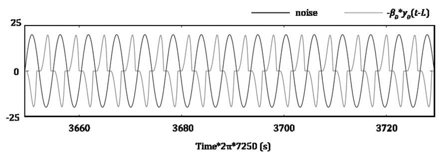
Figure 11 Output of the designed neural oscillator and noise component.
Figure 12 shows the result of noise cancellation using the
original output of the neural oscillator. In this simulation, ε
=0.0002 βD = 20/7, L = 5.5s. In the figure the unnecessary component
was reduced by the effect of the proposed filter, but discontinuous
changes can be seen due to the non-linear property
of the neural oscillator. This non-linear oscillator — having a
sinusoidal input — has a limit cycle. If “phase” is pre-defined on
the limit cycle, the phase and amplitude of the neural oscillator
as a sinusoidal wave can be constructed by the defined “phase.”
To realize this construction, a phase map was used (Ref. 14).
Figure 13 shows the result of noise cancellation using the constructed
sinusoidal wave by the neural oscillator and the phase
map. As can be seen, the original vibration of gear meshing is
reconstructed.
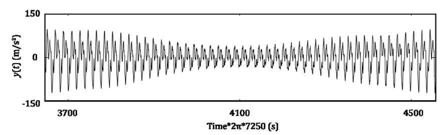
Figure 12 Result of noise cancellation using output of the neural oscillator.
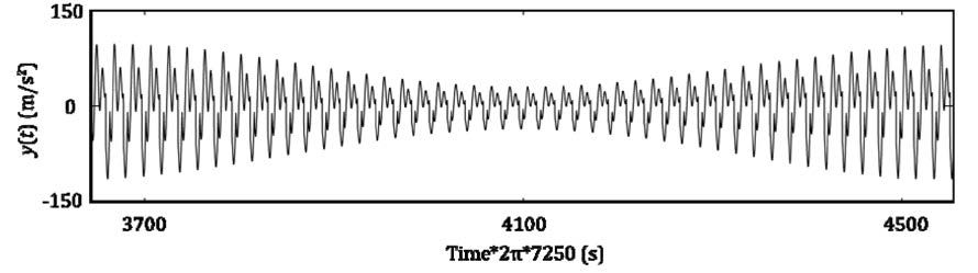
Figure 13 Result of noise cancellation using the constructed sinusoidal wave by the oscillator and phase map.
Conclusions
This paper proposed a new method using neural oscillators to
filter out the background noise of vibration in meshing plastic
gear pairs for detection of gear failure signs. It was shown how
to eliminate unnecessary frequency components, with a feedforward
control system providing a neural oscillator’s synchronization
property. Each neural oscillator is designed to tune the
natural frequency to a particular frequency of unnecessary components.
The designed neural oscillators can follow the change
in the driving torque variation autonomously, using their synchronization
property. Moreover, the output of the oscillators
is set to have a difference in the phase of 180 degrees from the
input, and is included in the original measured response to
reduce the amplitude of unnecessary components. The proposed
noise cancellation method applied to the simulated
response, and it was concluded that the proposed system could
sufficiently eliminate unnecessary vibration content.
In future works we will design the suitable input and output
gain for these oscillators, which could be determined through
trial and error, and will confirm the oscillators’ tracking properties.
Furthermore, we will validate the multiple-elimination of
unnecessary components and will apply the advanced system to
the acceleration response measured by operating tests of gears,
and assessing the efficacy of the system.
Acknowledgements. The authors gratefully acknowledge the
support of the department of mechanical and system engineering
at the Kyoto Institute of Technology and Mitutoyo Association for
Science and Technology, R1301.

Hidetaka Hiramatsu is a student in Mechanical
and System Engineering at Kyoto Institute of
Technology, received his bachelor degree in
mechanical engineering from Kyoto Institute of
Technology in 2014. His research interest is gear
failure detection by vibration analysis.

A PhD candidate student in design engineering
at Kyoto Institute of Technology (KIT), Junichi
Hongu began research in 2010 on application
of neural oscillators for vibration control at
KIT’s Precision Manufacturing Laboratory. He
subsequently in 2013 became a member of the
project team researching gear failure by vibration
analysis.

Daisuke Iba, associate professor of mechanical
and system engineering at Kyoto Institute
of Technology, received his Ph.D. degree in
mechanical engineering from the institute in 2005,
and his bachelor and master degrees in mechanical
engineering from Hosei University in 1995 and 1997,
respectively. Iba’s research interests are structural
response control and health monitoring, gear
system condition monitoring and smart gear sensor
development.

Arata Masuda, professor of mechanical
engineering at Kyoto Institute of Technology,
received his Ph.D degree in mechanical engineering
there in 1999, and his BS from Kyoto University in
1990. His research has been in the area of smart
structural systems and structural intelligence,
including structural health monitoring, machine
condition monitoring, vibration energy harvesting,
vibration control and human motion monitoring and assistance.

Prof. Dr.Eng. Ichiro Moriwaki is a professor
of mechanical and system engineering at Kyoto
Institute of Technology and the director of the KIT
Liaison Center. He received a doctorate degree of
engineering from Kyoto University in 1989. He was
the chairman of gearing committee in JSME in 2011-
2013, and still a member of the committee. Moriwaki
is also chairman of ISO / JIS standards committee in
JGMA, a Japanese delegate for ISO TC 60.

Morimasa Nakamura has a Ph. D in engineering
and is an assistant professor at the Kyoto Institute of
Techonology. His primary research field is tribology,
surface treatment technology and gearing.

Prof. Akira Sone earned his bachelor’s, master’s
and Ph.D. degrees in mechanical engineering at
Tokyo Metropolitan University in 1981, 1983 and 1987,
respectively, working there as a research associate
from 1987 to 1989. He has been on the faculty of the
mechanical and system engineering department
at Kyoto Institute of Technology since 1989. He has
been an associate professor and a professor there
since 1991 and 1999, respectively. Sone’s research
focus is seismic engineering and structural response control.
References:
- Iba, D., S. Ohmori, J. Hongu, M. Nakamura and I. Moriwaki. “Failure
Detection of Plastic Gears Based on a Comparison of Fourier Coefficients
of a Gear Mesh Vibration Model by Rectangle Pulse Train and Frequency
Analysis of Acceleration Response,” 2013 Trans. of the Japan Society of
Mechanical Engineers Series C. 79-808, 5138-5148, http://dx.doi.org/10.1299/
kikaic.79.5138.
- Shik, M. L. and G.N. Orlovsky. Neurophysiology of Locomotor Automatism,
Physiol. Rev., 1976, 56, 465-501.
- Matsuoka, K. “Sustained Oscillations Generated by Mutually Inhibiting
Neurons with Adaptation,” Biological Cybernetics, 1985, 52, 367-376.
- Matsuoka, K. “Mechanisms of Frequency and Pattern Control in Neural
Rhythm Generators,” Biological Cybernetics, 1987, 56, 345-353.
- Taga, G., Y. Yamaguchi and H. Shimizu. “Self-Organized Control of Bi-Pedal
Locomotion by Neural Oscillators in Unpredictable Environment,” Biological
Cybernetics. 1991, 65, 147-159.
- Fukuoka, Y. and H. Kimura. “Adaptive Dynamic Walking of a Quadruped
Robot on Irregular Terrain based on Biological Concepts,” 2003,
International Journal of Robotics Research, 22-3-4, 187-202.
- Iba, D. and J. Hongu. “Structural Vibration Control by Tuned Mass Damper
Using Central Pattern Generator,” 2011 Proc. SPIE 7981, Sensors and Smart
Structures Technologies for Civil, Mechanical, and Aerospace Systems, 79814Q.
DOI:10.1117/12.880406.
- Hongu, J. and D. Iba. “Mutual Synchronization Between Structure and
Central Pattern Generator,” 2012 Proc. SPIE 8345, Sensors and Smart
Structures Technologies for Civil, Mechanical, and Aerospace Systems, 83451E.
DOI:10.1117/12.915045.
- Kuramoto, Y. Chemical Oscillations, Waves, and Turbulence, 2003, Dover
Press.
- Pikovsky, A., M. Rosenblum and J. Kurths. Synchronization: A Universal
Concept in Non-Linear Sciences, 2001, Cambridge University Press.
- Umezawa, K., T. Sato and S. Ishikawa. “Simulation on Rotational Vibration of
Spur Gears,” 1983 Transactions of the Japan Society of Mechanical Engineers,
Series C. 49-441, 794-802 Series C.
- Ishikawa, J. “On the Deflection of Gear Teeth,” 1951 Transactions of the Japan
Society of Mechanical Engineers, 17-59, 103-106. http://dx.doi.org/10.1299/
kikai1938.17.59_103.
- Nishida, N. and Y. Maruki. “The Characteristic of Noise Spectrum of
Gears with Eccentric Errors,” 1981 Transaction of Japan Society of Precision
Engineering, 51 (3), 547-552.
- Hongu, J., D. Iba, M. Nakamura and I. Moriwaki. “Vibration Control of
Structures by a Dynamic Absorber Using a Neural Oscillator (Specification
Method of Dynamic Absorber’s Stroke Width Using an Amplitude Map), The
56th Japan Joint Automatic Control Conference, 2013, CD-ROM, No.129.