Gear Mesh Assembly
Gear Mesh Assembly
When assembling a pair of gears, what is a good method for setting and checking their mesh?
Expert response provided by: Robert Wasilewski, Arrow Gear Company.
Proper setting of gears usually involves checking backlash and tooth contact pattern. Backlash can be checked using a dial test indicator applied to a tooth on one member of the mesh and moving that member back and forth while holding the other member still. Contact pattern checks require painting some or all of the teeth of at least one member with gear marking compound and rotating the gears to see how they contact in the marking compound.
That’s the simple answer.
What do you do if you do not like the results you get? This really depends on the type of gears that you are assembling. Parallel axis gearing, spurs and helicals usually offer very little opportunity for change. Most of the time, the two supporting shafts are fixed in their relationship to each other by the location of the gearbox support bearings; all you can do is move the shafts axially in relation to each other. If the gears have crowning, the axial movement can be used to center the contact pattern. The backlash is controlled by tooth thickness and center distance. Since neither can be changed, you cannot adjust backlash; all you can do is measure the backlash in several positions to make sure whatever variation present is acceptable.

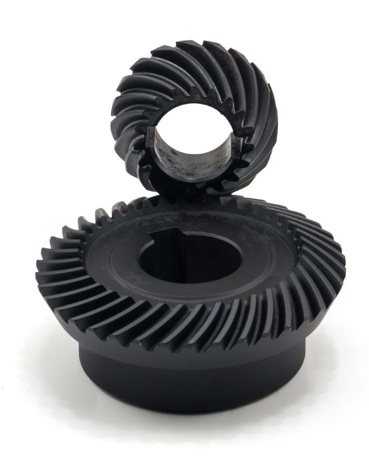
Desirable Bearing Pattern
- Click image to Enlarge
Non-parallel axis gearing is another story. While the shafts are still fixed in their relationship to each other, axial movement can greatly affect the contact pattern and the backlash. This is true for worm, hypoid and bevel gears. How do you get proper contact and backlash? By mounting the gears at the position the manufacturer made them at. Traditionally, bevel and hypoid gears have their mounting dimensions marked on each part. When this is the case you should use those dimensions by measuring the gearbox components that affect the position of the gears and calculate the thickness of any shims used to adjust their position; the shims are generally under bearing retainers or housing flanges. If shims are not in the design, components may have to be machined to adjust the gears position. The most common component to be machined would typically be a steel spacer. It is very important to note that you need to measure the individual components you are using, and do not just use the nominal dimensions from the component drawings. A little bit of adding and subtracting will show that the stack-up of tolerances from all the components can easily place the gears in the wrong position. If you measured correctly and calculated the shim or spacer width correctly, you should get the same contact pattern and backlash the manufacturer put in to the gear set. If you are rebuilding a gearbox, do not just put back the old shims or spacers without verifying they are the right thickness.