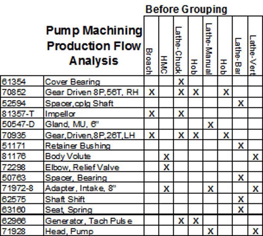
Figure 3a—Initial product–process matrix before grouping to identify part families. (Source: https://strategosinc.com/RESOURCES/06-Cellular_Manufacturing/gt-production_flow_analysis.htm)
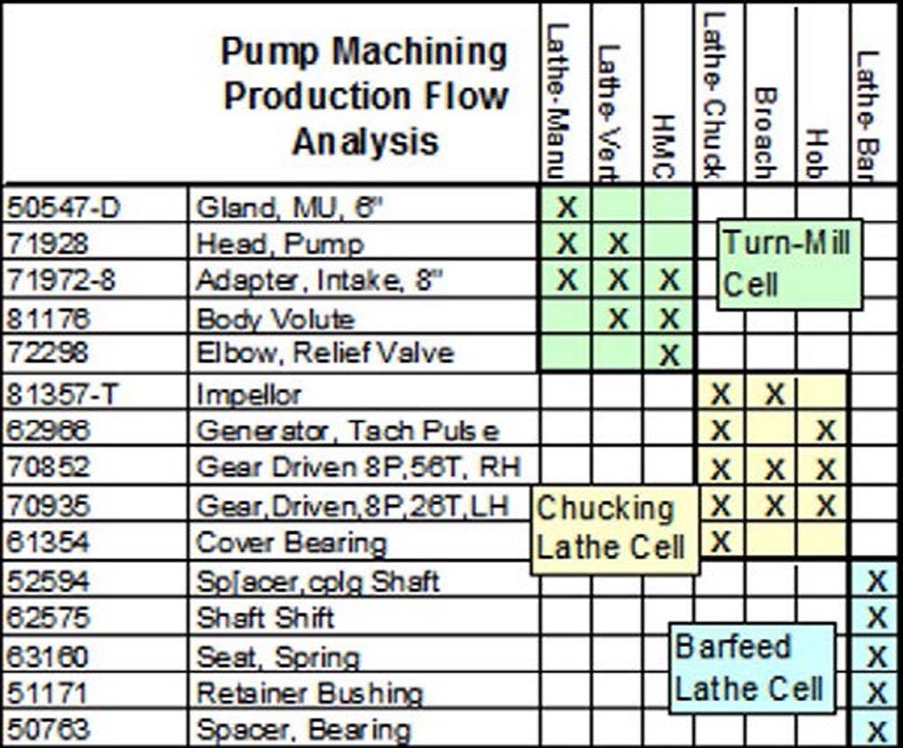
Figure 3b—Final product–process matrix after grouping to identify part families. (Source: https://strategosinc.com/RESOURCES/06-Cellular_Manufacturing/gt-production_flow_analysis.htm)
Exploit the cellular layout of the shop floor to foster a culture of teamwork: The key to successful implementation of a cell is to colocate all its machines, personnel and support services in one area. Figure 4a and Figure 4b display the material flows for the part family that was being produced in a machining cell before and after re-layout, respectively. If a cell is implemented with management’s support, it will 1) have manufacturing focus, 2) retain operational flexibility bounded by the parametric limits of a part family, 3) foster a culture of continuous improvement within a group of employees that accepts performance metrics that do not promote selfish, individualistic and elitist behavior, 4) promote a sense of ownership in every member of the cell’s team and 5) encourage management to give some level of self-governance and autonomy to the cell’s team so they can complete and ship products to their customers. But, from a management perspective, if they wish to discuss performance or delivery issues involving a certain part family, they will need to take much shorter walks by visiting that one cell which is producing those parts.
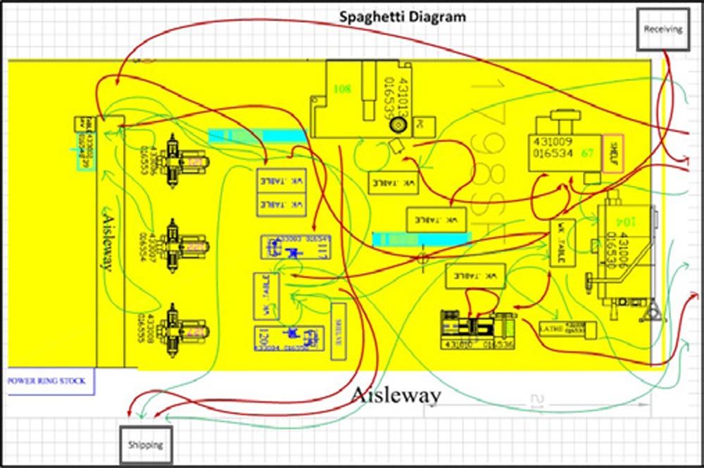
Figure 4a—Material flows for a part family prior to implementation of its machining cell.
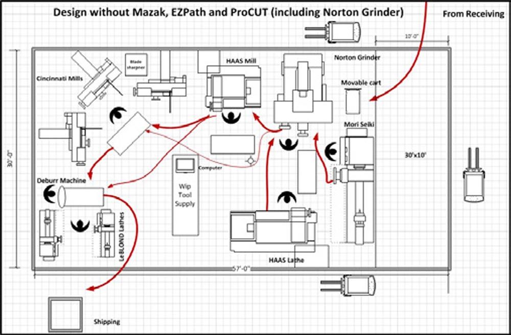
Figure 4b—Material flows for a part family after implementation of its machining cell.
Right-size nonmachining processes to absorb them into the cells: In general, like all other job shops, gear manufacturing job shops tend to focus on improving delivery performance and profitability by acquiring multimillion dollar metal-cutting machines. Most often, it is the manual machining processes, such as saws and drills, the inspection department and nonmachining processes, such as heat treatment, electroplating, coating, washing/cleaning, etc. that are often the root cause for their long delivery times.
Right-sizing a process that is currently external to a cell, such as washing, painting, deburring, inspection, etc. would allow it to be brought into the cell. This will have a significant impact on quality, delivery time and work-in-process. Also, it would improve the morale and job satisfaction of the cell personnel. Now, their team’s performance will not be affected by the workmanship and schedule priorities of those who work in other cells and/or external departments whose services are shared by all the cells.
Unfortunately, there are limitations with right-sizing the equipment used in any machine shop. Processes like heat treatment, electroplating or welding don’t lend themselves to being colocated with CNC machines in a cell. Maybe deburring could be in a corner of the cell if it was contained within a sound-proofed chamber having a dust collection system. Even the affordability of the smaller equipment could be a constraint since a single monument would be replaced by multiple workstations (or machines) given to all the cells whose parts use that process.
Will the day come when the inspection department in a gear job shop can be right-sized and that department is eliminated altogether? The inspection department, which has zero visual connectivity with the rest of the shop due to its location in a corner of the typical job shop, is often the real bottleneck in the shop. Can a CMM and other inspection devices be put on a mobile truck that travels around the shop? If that were possible, then inspectors would receive electronic requests from machinists and go to their cells to perform FAI (first article inspection). Also, while there is an abundance of machine monitoring systems on the market (FactoryWiz.com, MemexOEE.com, FORCAM.com, MachineMetrics.com) that are compatible with all CNC machines, it is unclear if these systems can monitor the “slow poke” CMMs that reside in any inspection department.
“Raze” and standardize the routings of all the parts within a part family: Every effort should be made to critique and re-engineer the routings of all the parts that have been grouped into a part family based on their similar (or identical) routings. First, the routings should be standardized by eliminating the differences in the machines used and the sequences in which the machines are used. Next, the routings should be standardized by eliminating the differences in the fixtures, tools, gauges, etc. used. Although my research is ongoing, I have reason to believe that the functional layout of any job shop could be replaced by a Hybrid Flexible Flow Shop. What will that do to simplify the chaotic material flows that are typical in any job shop? Say you were to go and stand on the roof of the job shop and look down at the material flows on their shop floor. Instead of the Spaghetti Diagram seen in Figure 2, the material flow of each job, regardless of the sequence of machines in its routing, will follow a linear path from one end of the shop to the other as is always the case on an assembly line.
Purchase a multifunction machine tool (or a flexible machining system) that combines two or more machines (or replaces an entire multimachine cell): It appears that metal removal rates remain the chief driver of a gear job shop’s capital investment choices. Unfortunately, this mindset of “keep making chips” results in the purchase of expensive new machines that 1) do not alleviate the shop’s capacity constraints, 2) do not increase throughput at their bottlenecks, 3) waste payroll dollars to keep employees busy producing WIP and 4) do not reduce the total distance that the typical order must travel all over the shop. Let us take the case of this family-owned machine shop in Houston that serves several customers in the oil and gas industry. The routing for the most complex component they make for a down-hole drilling tool assembly is Saw→Hole Drilling and Boring (Vendor Op)→Manual Lathe→CNC Lathe→CNC Mill→Shaper→Inspect→Ship. But they make other components that may have a routing like Saw→Manual Lathe→CNC Lathe→Inspect→Ship or a routing like Saw→CNC Lathe→CNC Mill→Inspect→Ship.
Editor’s Note:In the second part of this feature article (August issue of Gear Technology), several more strategies will be suggested that could guide any gear manufacturer/job shop to re-think their product mix, shop floor layout, current manufacturing technology investments, management policies, outsourcing decisions, employee training and development, etc. prior to investing in IoT software and/or technology. The author encourages gear manufacturers to post any lean questions they may have for a future article in Gear Technology. Submit your questions to shahrukhirani1023@yahoo.com or jaster@agma.org. |
Should this job shop buy a new CNC lathe with higher metal removal rates so the manual lathes department can be eliminated? Or should it buy a CNC turning center that combines the operations done on the CNC lathe and CNC mill? Or should it explore how to eliminate the shapers by using their CNC mills to cut the internal splines on some of their parts? Having observed the WIP in the three buildings that comprise this machine shop, the CNC lathes department is not the shop’s bottleneck. Plus, they have a classic process layout. So, the purchase of a high-priced CNC lathe with a faster metal removal rate and in-cut spindle time would not reduce their WIP nor help them to quote shorter lead times. Guess what their management team eventually did to drastically reduce delivery times? They 1) eliminated the manual turning department by moving their work to the larger CNC lathes and 2) re-organized the shop into three cells as follows: Cell #1, CNC Turning; Cell #2, CNC Turning→CNC Milling; Cell #3, CNC Turning→CNC Milling→Spline Cutting.
Instead of their prevailing fixation with metal removal rates and machine utilization, gear job shops should buy multifunction machines and systems that combine consecutive operations currently being done on different machines—especially if those machines are currently located in separate departments, such as CNC lathes and CNC mills. By combining machines, the significant delays due to 1) material handling between several machines, 2) waiting for material handlers to pick up and move a batch of parts from one machine to another, 3) batch-and-queue production flow, 4) setup and gauging at every machine, 5) waiting in queue at machines that are shared by multiple part families, etc. are reduced.
For example, in the case of the family-owned machine shop discussed earlier, given the many pallets loaded with turned parts machined by their CNC lathes, I tried to impress upon their GM to limit new orders released to that department every day. This is what I told the GM of that shop, “Are you in the business of keeping your lathe operators busy making parts? Or should you focus on completing and shipping as many parts as you can every day?”
So how could a job shop make a major investment to upgrade equipment on their shop floor by buying a new machine or system that reduces material flow? By first selecting a cell that currently produces a family of parts and later reducing the number of separate machines in it. If you are a gear job shop, have you done a product-process matrix analysis of your product mix to find any part families that could each be produced in a standalone cell (shop-within-a-shop)? In fact, go to the floor and ask a couple of your shop supervisors to scope out a potential family of gears (for example, splined shafts). Next, draw a material flow map and compute workloads on the different machines for the machines that would be put in their cell. Now, identify a set of two or three machines that perform consecutive operations that appear in the routings of that family of gears. For all those operations that would have to be done on a single machine, prepare the list of specifications (work envelope, axes of freedom, number of tools, in-process gauging, etc.). Finally, present that list of specifications to the different machine tool vendors, such as Mazak, Okuma or Mori Seiki, who could build the multifunction machine (or system). Do they come back to you with any multitaskers that they could build for you?
leanandflexible.com