Component-specific errors, on the other hand, are not foreseeable. They are noticeable by sudden deviations in one or more quality criteria. This can be caused by grinding screw breakouts, blank defects or set-up errors.
Since in highly efficient manufacturing processes such as rolling grinding, the actual machining of a gear wheel takes much less time than the control measurement, 100% of all components cannot be tested. In addition, as described at the beginning, the quality requirements for gears for electric transmissions are extremely high.
“The required tolerances of profile angle, flank line angle, concentricity, two-ball dimension are sometimes smaller by a factor of 3 than in the conventional drivetrain. With the flank line angle error fHß, a typical requirement is ±4 μm, with combustion engine transmissions this was sometimes ±13 μm,” Wölfel described the requirements of his customers. Together with the required machine and process capabilities, these quality requirements are on the edge of what is technically and economically feasible. And even static and dynamic stability of the processing machine and process cannot be increased arbitrarily. The only way out is to start with the analysis and control methods. Otherwise, the following applies: The tighter the tolerance limits become with the same machine/process capability, the greater the number of measured components must be. However, this is associated with great effort. And finally, a downstream component inspection is not adding value.
The closed loop has already established itself as an important tool today. This accelerates and improves the feedback between downstream gear measurement and the processing machine itself. Here, the results of the test are no longer printed out on the measuring machine and made available to the machine operator for evaluation on paper, but are transmitted directly to the processing machine as a standardized file. The grinding machine then independently decides on the basis of pre-selectable tolerance corridors whether the process needs to be intervened at all, for example with scalable correction values. If unexpectedly high deviations from the target geometry occur, the decision to proceed is then again up to the operator himself (Figure 1).
The arbitrator at the end of the manufacturing process
At the end of the manufacturing process of a complete gearbox, there is a so-called end-of-line test bench. There, not only individual gears are tested for their quality, but fully assembled gearboxes are evaluated. They undergo various test cycles that simulate subsequent operation in the vehicle. The operating noise is also recorded. Through a corresponding evaluation of this data, acousticians can read out intervention conditions, typical frequencies and possible disturbing noises.
“Unfortunately, gearing errors are only noticed at the end of the manufacturing process,” Wölfel added. “Then the complete gearbox has to be dismantled, the individual components checked and, based on this, analyzed to determine which component is responsible for the conspicuousness on the test bench. A complete batch of components may also cause problems. However, this is only noticeable when the entire value chain has already been completed.”
 Figure 1 - Tolerance corridors for the closed loop.
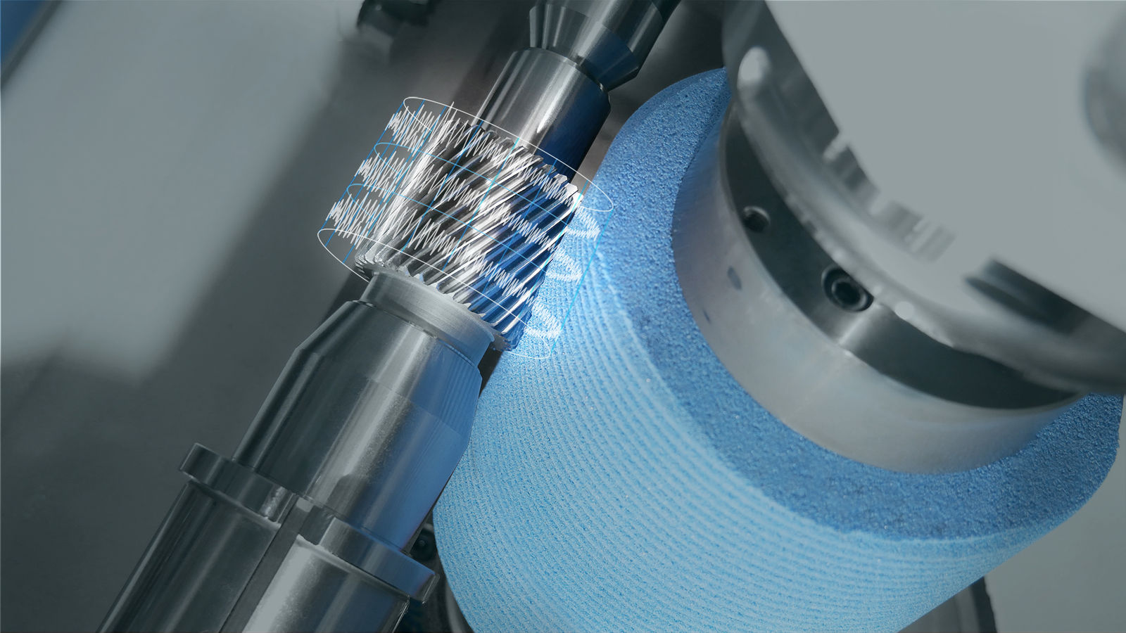
Today, there are certainly ways to identify components that could cause noise before they are installed in the transmission. A very common method in electric drives is the so-called waviness analysis on gear surfaces. Profile, line and pitch measurements are carried out on all teeth on the gear measuring machine and strung together in such a way that the gear wheel is mapped over its entire circumference. By means of mathematical methods, the ripple on the gear wheel can be detected. However, starting with the complete measurement of the gears, this method is very time-consuming and therefore unsuitable for 100 percent testing in series production.
“The grinding time of typical e-transmission components is less than one minute, while the measuring time is four to six minutes; with an all-tooth measurement as the basis of a ripple analysis even significantly more. And finally, a downstream component inspection is not value-adding. What is needed here is a further development of the in-process analysis, which already allows conclusions to be drawn about the generated component quality during machining,” Wölfel said.
Detect possible noise problems already during processing
A promising approach is actually to identify possible errors during grinding. Process monitoring is the ‘buzzword.’ Stegner explained this approach: “We already have numerous sensors and measuring systems in the machine that can provide us with a lot of signals, measured values and information. At the moment, we only use them primarily to operate the functions of the machine. In the future, however, we also want to use them to assess the machining process directly in the machine.”
However, this does not mean integrating an additional tactile measuring function into the grinding machine in order to achieve a faster closed loop. Nor is it a question of testing and evaluating a ground component directly in the machine and correcting any deviations in the production of further components. The focus is rather on the analysis of the machining process in real time to detect deviations from a previously defined reference process. However, it is not enough to define only envelope curves for signals from the machine. This can be explained by way of example using the signal ‘Current consumption of the grinding spindle’ in Figure 2. This signal can be used to detect a possible flank line angle error (fHß) at an early stage. “However, the method of envelope detection reaches its limits here, as the error is difficult to identify. As long as the signal remains within the envelope, no alarm is triggered. So, you need a more intelligent form of evaluation. An artificial intelligence that tries to recreate human decision-making structures. He makes decisions from a variety of different information — superimposed with his experience — according to which he acts,” Stegner said.
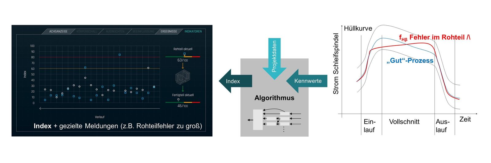 Figure 2 - Error analysis and index calculation in the machining process.
Process monitoring: Intervene before it is too late
Process monitoring can be defined as component-specific monitoring and evaluation of the grinding process. As described, it is not trivial to generate instructions for action from the sensor signals. But it is possible. Various characteristic values can be formed from time signals. In the simplest case, these can be maximum or root mean square (RMS) values of the signals. The characteristic values are then combined with the known project data via algorithms and processed into indices, for example, into a noise or screw breakout index.
“For noise-critical components, an order analysis similar to the order spectrum on an end-of-line test bench can be created via fast Fourier transformation (FFT). This allows the recorded signals to be better classified and related to results on the transmission test bench (Figure 3). Nonprepared measurement data have no use,” Stegner explained specifically about transmission noise.
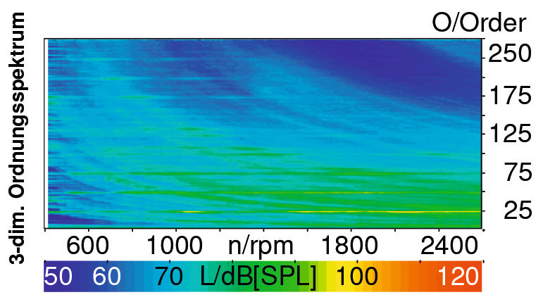 Figure 3 - Order spectrum taken on a gearbox test bench.
In the end, especially in the manufacturing environment, only appropriate indices help to identify very specific errors.
Benefits of process monitoring therefore can be determined by 100 percent testing of all components, the identification of abnormalities still in the grinding process, detection of component-specific errors, targeted reporting of irregularities, adaptive intervention in the process and parts tracking.
Next step: Standardization
Process monitoring is not yet an app that can be easily downloaded and used. Rather, it is a customer- and application-specific development that defines and monitors indices related to the respective component. But even this first step is much more than was thought feasible until recently.
“Several pilot customers are already using this functionality today. We can currently already detect various errors and also intervene on the process side. In addition, we are already working on ensuring that the grinding machine learns characteristic values for new components itself. Of course, this requires broad experience from fault patterns, the geometric quality of the components and corresponding feedback from the transmission test bench,” Stegner said.
“The next goal is that the user can use this functionality even without our component-specific support. It is also important to understand that process monitoring, and the closed loop do not contradict each other, but complement each other,” Wölfel said.
Both approaches to process-integrated quality assurance are already available for Kapp Niles machines today and are continuously receiving further functional scopes and possibilities of use through the experience gained from series production.
kapp-niles.com
(Additional edits by Matthew Jaster, Senior Editor, PTE and Gear Technology)