and
 (4)
(4)
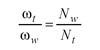
here s is the machine radial setting. The second set of related motions is the rotation of the generating gear and rotation of the work. Such a related motion is called rolling or generating motion and is represented as
 (5)
(5)
where Ra is called the ratio of roll. Basically, the second set of related motions provides generated tooth geometry in the profile direction.
In the non-generating (Formate ®) face hobbing process, only the first set of motion or indexing motion is provided for the gear tooth surface generation. Therefore, the gear tooth surfaces are actually the complementary copy of the generating tooth surfaces.
Tool Geometry
The Gleason face hobbing process uses TRI-AC® or PENTAC® face hobbing cutters.Face hobbing cutters are different from face milling cutters. The cutter heads accommodate blades in groups. Normally, each group of blades consists of an inside finishing blade and an outside finishing blade with reference point M located at a common reference circle, and the blades are evenly spaced on the cutter head (see Fig. 4).

Figure 4--Face hobbing cutter head and blades.
In some specially designed cutter heads, the inside and outside blades are not evenly spaced and therefore the blade radial position is correspondingly adjusted. Basically, the tool geometry can be defined by the major parameters of the blades and their installation on the cutter heads. Since the face hobbing tooth surfaces are kinematically generated by the cutting edges of the blades,an exact description of the cutting edge geometry in space is very important. The blade edge geometry can be described in the coordinate system St that is connected to the cutter head with rotation parameter Θ. The major parameters that affect the cutting edge geometry are:nominal blade pressure angle α, blade offset angle δ, rake angle λ, and effective hook angle κ.
Figure 5 shows a basic geometry of the inside and outside blade edges, which are represented in the coordinate system Sb that is fixed to the front face of the blade. The origin Ob coincides with reference point M at reference height hb. Generally, the blade geometry consists of four sections: (a) tip, (b) Toprem®, (c) profile, and (d) Flankrem.

Figure 5--Blade geometry.
Sections (a) and (d) are circular arcs with radii re and rf respectively. Sections (b) and (c) can be straight lines, circular arcs, or other kinds of curves. Section (c) generates the major working part of a tooth surface. Toprem and Flankrem relieve tooth root and tip surfaces in order to avoid root profile interference and tooth tip edge contact. In order to obtain a continuous tooth surface, the four sections of the blade curves should be in tangency at connections. For a current cutting point P on the blade, the position vector and the unit tangent can be defined in the coordinate system Sb ,
 (6)
(6)
 (7)
(7)
where u is the parameter.
Equations 6 and 7 can be represented in the cutter head coordinate system St, as
 (8)
(8)
 (9)
(9)
here matrix Mtb denotes the coordinate transformation from Sb to St. Coordinate system Si is used to represent the rotation of the cutter head with an angular displacement Θ. From Figure 4, one can obtain the transformation matrix Mit and represent the blade geometry in system Si as
 (10)
(10)
 (11)
(11)
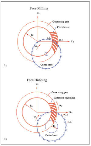
Kinematical Simulation of Face Hobbing Indexing Motion
As described above, the indexing motion generates the cutting path or the tooth lengthwise curves that are called the extended epicycloids (see Fig. 3). The indexing motion can be simulated and visualized in terms of the motion relationship between the generating gear and the cutter. Furthermore, such a motion can be represented in the cross-section plane that intersects the blade edges at the reference point M and is perpendicular to the axis of the generating gear so that the motion can be visualized on a plane, as shown in Figure 6.

Figure 6--Simulation of face hobbing indexing motion.
The simulation is based on the following matrix transformation, which represents the relative motion of the cutter head with respect to the generating gear.
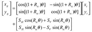 (12)
(12)
The coordinate system Sg is connected to the generating gear (Fig. 6), and xg and yg are the coordinates of the tooth lengthwise curves, i.e., the extended epicycloids. Coordinates xt and yt specify points on the blades in system St. SH and SV are the initial horizontal and vertical settings of the cutter head. Giving a value to parameter Θ corresponds to a specific cutting position. Figures 6 (a) and (b), respectively, show a single cutting position and multiple cutting positions, from which the kinematical generation of tooth lengthwise curves and the tooth slots can be visualized.
Modeling of Face Hobbing Tooth Surface Generation
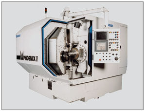
The face hobbing process can be implemented on the Gleason Phoenix® series CNC hypoid machines (see Fig. 8).

Figure 8--Gleason Phoenix® II 275HC hypoid gear generator.
The machine tool settings and the tooth surface generation model can be derived based on traditional cradle-style mechanical machines. Computer codes have been developed to "translate" the machine settings, and CNC hypoid gear generators move together in a numerically controlled relationship with changes in displacements, velocities, and accelerations to implement the prescribed motions and produce the target tooth surface geometry.
In this paper, a generalized face hobbing kinematical model is developed. The proposed model, shown in Figure 9, is based on the mechanical spiral bevel and hypoid gear generators.

Figure 9--A kinematic model of mechanical hypoid gear generators.
The model consists of eleven motion elements, which are listed in Table 1. The cradle-style represents the generating gear, which provides generating roll motion between the generating gear and the generated work. In the non-generated (Formate®) process, the cradle is held stationary.

Face hobbing machine settings are: (1) ratio of roll Ra; (2) sliding base Xb; (3) radial setting s; (4) offset Em; (5) work head setting Xp; (6) root angle γm; (7) swivel j; and (8) tool tilt i. Although the kinematical model in Figure 9 is based on the cradle-style generators, considering the universal motion ability of CNC machines, the machine settings can be generally represented as
 (13)
(13)
 (14)
(14)
 (15)
(15)
 (16)
(16)
 (17)
(17)
 (18)
(18)
 (19)
(19)
 (20)
(20)
The first terms in Equations 13-20 represent the basic constant machine settings and the second terms represent the dynamic changes of machine setting elements, which might be kinematically dependent upon the motion parameters of the cradle rotation angle φ. In current practice, higher order polynomials are used (Ref. 2). These motions can be realized through computer codes on the CNC machine. Equations 13-20 provide strong flexibility for generating all kinds of comprehensively crowned and corrected bevel gear tooth surfaces.
Matrix Representation of Motion Elements
In order to mathematically describe the generation process,the relative motions of the machine elements and their relationship have to be represented by a series of coordinate transformations established and rigidly connected to each motion element listed in Table 1. In current pratice, higher polynominals are used (Ref. 2). System Sm is fixed to the machine frame 1 and is considered as the reference of the related motions. System Ss is connected to the sliding base element 11 and represents its translating motion. System Sr is connected to the root angle setting element 10 and represents the machine root angle setting. System Sc is connected to the cradle and represents the cradle rotation with parameter φ. System Sp is connected to the work head sliding setting element 9 and represents the work head setting motion. System So is connected to the work head offset setting sliding element 8 and represents the work head offset setting motion. System Sw is connected to the work 7 and represents the work rotation with angular parameter ψ. System Se is connected to the eccentric setting element and represents the radial setting of the cutter head (see Fig. 11(a)). System Sj is connected to the tilt wedge base element 5, which performs rotation relative to the eccentric element to set the swivel angle j (see Fig. 11 (b)). System Si is connected to the cutter head carrier, which performs rotation relative to the tilt wedge base element to set the tool tilt angle i (see Fig. 11 (c)).

Figure 11--Relationships of coordinate systems Sm, Se, Sj and Si.
During tooth surface generation, at each cutting instant, a point on the blade edge generates a corresponding point on the work tooth surface. Through the
coordinate transformation from Si to Sw, the current cutting point P can be represented in the coordinate system Sw, namely,
 (21)
(21)
 (22)
(22)
where Mwi (Θ, φ, ψ) is a resultant coordinate transformation matrix with three parameters and is formulated by the multiplication of the following matrices representing the sequential coordinate transformations from Si to Sw,
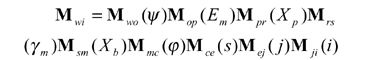 (23)
(23)
where matrices Mwo, Mop, Mpr, Mrs, Msm, Mmc, Mce, Mej and Mji can be obtained directly from Figures 12 and 13 and Equations 21 and 22 can
be simply re-written as
 (24)
(24)
 (25)
(25)
here subscript "w" denotes that the vectors are represented in the coordinate system Sw.

Figure 12--Pinion and gear tooth surfaces of a face-hobbed hypoid gear drive.

Figure 13--A TCA output interface.
Tooth Surface of a Non-Generated (Formate)Member
As discussed above, the non-generated (Formate)gear tooth surface is the complementary copy of the generating gear tooth surface, which is kinematically formed as the cutting path of the blade edge along an extended epicycloid lengthwise curve. In Formate gear generation, the cradle is held stationary and parameter φ is assumed to be zero. Therefore, Equations 24 and 25 can be re-written as
 (26)
(26)
 (27)
(27)
which give the position vector and a unit tangent at the current cutting point P on the gear tooth surface. The unit normal of the gear tooth surface can be derived as
 (28)
(28)
where
 (29)
(29)
which represents the unit vector of hobbing speed. Equations 26-29 provide equations of position vector, unit tangent, and unit normal of a non-generated gear tooth surface.
Tooth Surface of a Generated Member
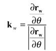
In addition to the relative hobbing motion or the indexing motion for a generated member, either gear or pinion, generating roll motion is provided and the generated tooth surface is the envelope of the family of the generating surface. The generated tooth surface can be represented as
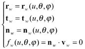 (30)
(30)
where nw is obtained from Equation 28, and the relative generating velocity vw is determined by
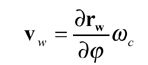 (31)
(31)
Equation fw(u, Θ, φ)=nwxvw=0 is called the equation of meshing (Ref. 4). Equation 30 defines the position vector, the unit normal, and the unit tangent at the current cutting point P on the generated work tooth surface. All these vectors are considered and represented in the coordinate system Sw that is connected to the work. A unit cradle angular velocity, i.e., ωc=1 can be considered. The equation of meshing is applied for determination of generated tooth surfaces.
Implementation of the Mathematical Models
Figures 12 (a) and (b) show geometric models of a pinion and a gear generated based on Equations 26-30. A very important application of the developed mathematical models is the development of tooth contact analysis for the face hobbed spiral bevel and hypoid gears. Tooth contact analysis (TCA) is a computational approach for analyzing the nature and quality of the meshing contact in a pair of gears. The concept of TCA was originally introduced by Gleason Works in the early 1960s as a research tool and applied to spiral bevel and hypoid gears (Ref. 7). Today, TCA theory has been substantially enhanced and generalized and applied in advanced synthesis of face milled spiral bevel gears (Refs. 8, 9).
Based on the developed mathematical models for face hobbing generation of spiral bevel and hypoid gears, an advanced TCA program for the face hobbing process has been developed for both non-generated and generated spiral bevel and hypoid gear drives. The program incorporates simulation of meshing of the whole tooth surface contact including the Toprem and Flankrem contact. Tooth edge contact simulation is also developed and included in the program. Figure 13 shows an example of the output interface of the advanced TCA. Typically, a TCA output illustrates bearing contact patterns on both driving and coast sides of the tooth surfaces and the corresponding transmission errors. Information on the gear drive assembling adjustments is also provided.
Conclusion
This paper presents the tooth surface generation theory of the face hobbing process. The kinematics of face hobbing indexing are described and simulated. A generalized spiral bevel and hypoid gear tooth surface generation model for the face hobbing process is developed with the related coordinate systems that are directly and visually associated with the physical motion elements of a bevel gear generator. The generation model covers both Gleason non-generating and generated methods of the face hobbing process. And, it can also be adapted for the face milling process. Based on the developed mathematical model, an advanced TCA is developed and integrated into Gleason CAGETM for the Windows system, which has been released worldwide.
References
1. Krenzer, T.J. "Face-Milling or Face Hobbing," AGMA Technical Paper, 90 FTM 13, 1990.
2. Stadtfeld, H.J. Advanced Bevel Gear Technology, The Gleason Works, Edition 2000.
3. Pitts, L.S.and M.J. Boch. "Design and Development of Bevel and Hypoid Gears using the Face Hobbing Method," Cat. #4332, The Gleason Works, 1997.
4. Litvin, F.L. Gear Geometry and Applied Theory, Prentice Hall, 1994.
5. Baxter, M.L. "Effect of Misalignment on Tooth Action of Bevel and Hypoid Gears," ASME paper 61-MD-20, 1961.
6. Krenzer, T.J. "The Effect of the Cutter Radius on Spiral Bevel and Hypoid Tooth Contact Behavior," AGMA Paper No. 129.21, Washington, D.C., October 1976.
7. "Tooth Contact Analysis Formulas and Calculation Procedures," The Gleason Works Publication, SD 3115, April 1964.
8. Litvin, F.L., Q. Fan, A. Fuentes and R.F. Handschuh. "Computerized Design, Generation, Simulation of Meshing and Contact of Face-Milled Formate-Cut Spiral Bevel Gears," NASA Report CR-2001-210894, ARL-CR-467, 2001.
9. Litvin, F.L.and Y. Zhang. "Local Synthesis and Tooth Contact Analysis of Face-Milled Spiral Bevel Gears," NASA Contractor Report 4342, 1991.
 Dr. Qi Fan is a bevel gear theoretician at The Gleason Works of Rochester, NY. Prior to that, he worked in the Gear Research Center at the Mechanical and Industrial Engineering Department at the University of Illinois at Chicago. Fan has authored more than 20 papers on bevel gear research.


 (1)
(1) (2)
(2)
 (3)
(3)