The most important roughness parameters
for flank measurements are shown
in Figure 5.
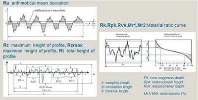
Figure 5 Roughness parameters according to DIN EN ISO 4287/13565.- Click image to Enlarge
The arithmetic mean roughness value
Ra is the ordinate value of the roughness
profile within a single measurement path
lr. The individual roughness depth Rz is
the sum of the distance between the profile
peak and profile valley within a single
measurement path lr. Like Ra, the averaged
roughness profile Rz is determined
as an arithmetic mean from the individual
measurement paths.
The total height of the roughness profile
Rt is the sum of the height of the largest
profile peak and the depth of the largest
profile valley within the measurement
path ln. The maximum individual roughness
depth Rmax is the largest individual
roughness depths Rz. The stock portion
Rmr is the ratio of the sum of the stockfilled
lengths Ml1-Mli for the total measuring
path ln as a percent value.
The core roughness depth Rk is the
depth of the roughness core profile. The
reduced peak height Rpk is the height
determined from the peaks projecting
beyond the core area. The reduced
peak depth Rvk is the height determined for the striations extending from the
core area into the stock. The parameters
Mr1and Mr2 of the stock percentage
curve characterize the stock content at
the limits of the roughness profile Mr.
Measuring Methods and
Measuring Equipment for
Roughness Measurement
In the VDI/VDE 2602 directive, and
the DIN EN ISO 4287 and DIN EN ISO
16610-21 standard, these are profile
methods that describe the properties of
the profile equipment and the generalcase
measurement conditions for roughness
measurements of surfaces.
Skid-less probing systems and instruments
with lateral skid (at the side off)
are typically used to measure flank
roughness (Ref. 1).
Figure 6 shows the tracing situation of
a skid-less probing system in the tooth
space. The profile here must be aligned
as parallel as possible to the tracing direction
of the test device. In the result, however,
there is always a difference between
the straight trace direction and the
curved flank. The overall profile must
therefore be corrected with a compensation
arc, or residual errors must be eliminated
with the lambda C profile filter.
The possible trace path is limited due to
the curved profile surface and the measuring
range of the roughness probe
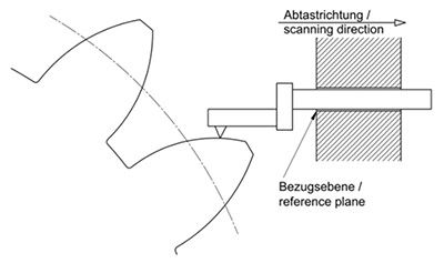
Figure 6 Skid less probing system with plane reference.- Click image to Enlarge
The probing conditions of a skid system
are shown in Figure 7. The sidemounted
probe skid follows the profile
of the tooth flank. A deviation due to
changing contact conditions during the
roughness measurement must be taken
into account here. The deviations are relatively
small, however, and are largely
eliminated due to profile filtering.
Figure 7 Probe system with side mounted skid probe (VDI/VDE 2612 Sheet 5).- Click image to Enlarge
For roughness measurement on cylindrical
gear flanks, measuring devices with
an involute reference (Fig. 8) offer certain
advantages. Logging of measured values
in profile generation mode on the tooth
flank (involute) ensures that the probe
tip is always aligned perpendicular to the
surface; thus the roughness can theoretically
be scanned over the entire profile
length. The disadvantage of this type of
contact operation, however, is that the
scanning speed for measured value logging
is not constant, nor is a uniform
measuring point distance ensured. But this is a minor disadvantage, resulting in
measured value differences of up to 10%.
Figure 8 Skid probe system with involute reference (VDI/VDE 2612 Sheet 5).- Click image to Enlarge
On current gear measuring centers, the
involute reference is generated via CNC
path control and can be used in principle
in conjunction with skid-less systems
and skid systems. For special profiles and
bevel gear flanks with other profile forms,
for instance, the CNC-guided path control
can also execute reference profiles.
Roughness Measurement Procedure in
Practice
The measuring conditions (Ref. 1)
must first be defined in order to achieve
generally comparable results. The following
points must be taken into account to
avoid measurement deviations:
- Probe system
- Profile filter
- Alignment of test specimen
- Environmental influences
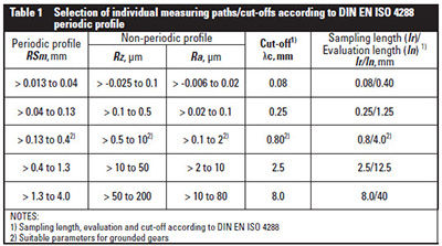
Refer to Table 1 to select appropriate
individual measurement paths and cutoff.
As finish-machined surfaces on tooth
flanks in particular must be tested, the
highlighted values should be used preferentially.
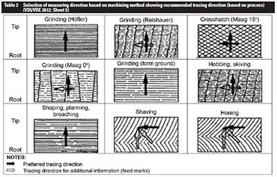
The measuring direction for
the roughness measurement should be
selected according to Table 2, based on
the machining method and the resulting
structures.
- Click image to Enlarge
- Click image to Enlarge
When selecting the appropriate parameters
for the roughness measurement on
tooth flanks, the stress on these surfaces
due to compression and sliding must be
taken into account. The parameter Rmax
has little meaning for this stress, as individually
projecting peaks, which are of
little relevance for the load capacity, are
taken into account here. The arithmetic
mean raw value Ra is greatly distributed,
but correlates the least with the function
parameters and therefore should not be
used. The preferred parameter for roughness
on flank surfaces is Rz, as it provides
a high degree of clarity and makes it possible
to draw accurate conclusions about
the height of the roughness profile.
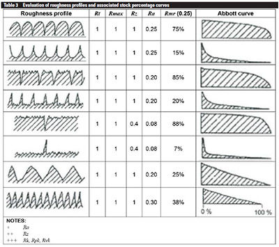
In addition to the parameters that
describe only the vertical expansion of
the roughness profile, it is important to
determine the roughness structure in
order to determine the wear behavior or
load capacity of a tooth flank. The stock
percentage curve (Abbott-Firestone)
and the resulting parameters Rk, Rpk
and Rvk are appropriate for determining
the structure of the roughness profile. A
nearly S-shaped pattern in the stock percentage
curve is ideal. Another appropriate
parameter for the stock percentage is
Rmr (c). See Table 3 for a comparison of
roughness parameters and stock percentage
curves.
- Click image to Enlarge
A standard roughness testing device
(Ref. 3) is shown in Figure 9. In addition
to a feed mechanism with a microprobe
system, the device also features a
cross-slide to position and test the workpiece.
An additional clamping fixture is
generally needed to test toothed gears.
According to the figure detail, compact
reference area probe systems with an
application range from module 0.5 can
be used here. A PC computing system
with high-performance software is available
to control and evaluate the roughness
measurements. The evaluation software
takes into account a large number of
established roughness measurement standards.
A report printout of the measuring
results can be custom-designed.
Figure 9 Standard roughness test device — example stationary surface measuring station for
gears (Mahr catalog).- Click image to Enlarge
One advantage of the device presented
is that general workpieces can also be
tested, and a higher standard overall is
provided for roughness measurement. It
does, however, require more set-up for
flank measurements and the device is not
suitable for large and heavy workpieces
(500 mm in diameter, for example).
Application example: cylindrical gear/
bevel gear measurement on gear measuring
centers. Gear measuring centers
are typically equipped with a rotary
table for testing rotationally symmetrical
workpieces and are suitable for measured
value logging on small to very large workpieces, in conjunction with a model
series. As previously described, the measuring
method used here is the involute
reference in combination with a skid system.
For roughness measurement a special
probe system on the adapter plate of the
measuring machine’s macro probe system
is adapted (Fig. 10). An additional electrical
connection is provided for transferring
the measured values from the integrated
micro-probe system for the roughness
measurement. For measured value
logging in the profile direction, the probe
skid rests on the flank to be tested and
executes a movement similar to a normal
profile measurement for the macrostructure
of the flank. As it does so, a diamond
needle located in front of the probe skid
logs the measured values for the roughness
measurement. The probe system
represented here is also suitable for measured
value logging in the tooth trace
direction. The roughness probe system
also features an adjustment mechanism
enabling the probe needle to be aligned
perpendicular to the surface for helical
cylindrical gears as well.
Figure 10 Roughness testing device (cylindrical gear) on gear measuring centers — roughness
inspection in profile direction (involute reference).- Click image to Enlarge
Thus in conjunction with an automatic
probe change rack, a fully automatic process
can be carried out for the roughness
measurement in combination with other
gear measurements. Because the measured
value logging is controlled by the
CNC-guided measuring axes, this results
in highly precise positional accuracy and
reproducibility for the measuring positions.
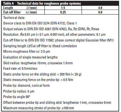
The most important technical data
for the integrated roughness test equipment
are shown in Table 4.
- Click image to Enlarge
To document the measuring results,
the roughness parameters can also be
documented on the standard measuring
sheet for profile and reference tooth
traces, or they can be printed as a separate
measuring sheet including diagrams
(Fig. 11).
Figure 11 Results output: roughness measurement on gear measuring centers.- Click image to Enlarge
Comparable to measured value logging
on cylindrical gears, roughness measurements
can also be conducted on bevel
gears. The profile measurement here
takes place based on the calculated nominal
data, which are available in high resolution
for measuring the macrostructure.
Various probe systems are used for
measured value logging, depending on the design of the bevel gears pinions/
ring gears. For pinion shafts a straight
probe system is used — exactly like
the probe system for cylindrical gears
(Fig. 12) — and an angled system is used
for ring gears.
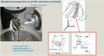
Figure 12 Roughness testing device (bevel gear) on gear measuring centers.- Click image to Enlarge
A fully automatic test sequence can
also be specified via the software operator
guidance. Measuring positions, measuring
paths, and the number of flanks to
be tested, etc., can be programmed individually
(Fig. 13). The measuring results
are displayed numerically on the screen
for the selected flanks (Fig. 14); measured
values can also be printed out with diagrams
(Fig. 15).

Figure 13 Operator guidance: roughness measurement on gear measuring centers.- Click image to Enlarge

Figure 14 Results output: roughness measurement on gear measuring centers.- Click image to Enlarge

Figure 15 Roughness bevel diagram.- Click image to Enlarge
Thus the device presented here offers
a reliable, convenient measuring method
for roughness measurement on spiral
bevel gears with spatially pronounced
curves. Large-module bevel gears can
also be tested in conjunction with suitable
probe systems.
Concluding Remarks
These important measured values can be
carried out quickly and easily in conjunction
with conducting roughness measurements
of tooth flanks on gear measuring
centers using the equipment presented
here.
Measurements on both smaller and
larger gear teeth can be taken in a single clamping in conjunction with standard
test parameters.
The measurement conditions for
standardized roughness measurements
are largely met by measured value logging
in the profile direction with CNCcontrolled
contouring in generation
mode for each tooth profile.
References
- VDI/VDE 2612; Sheet 5. Measurement
and Testing of Gearings: Surface Roughness
Measurement of Cylindrical Gears and Bevel
Gears by Means of Stylus-Type Instruments
(Release 2014/2015).
- Jenoptik publication.
- Mahr publication. “Mar Surf XR 20 Roughness
Testing Device
About Author
Dipl.-Ing. Günter Mikoleizig currently heads the product
management and application engineering department for gear
inspection machines at Klingelnberg GmbH, Germany. With more
than 30 years in the field of gear inspection technology, he is
fully experienced with the design and development of inspection
machines and their product management. He in fact developed
a product line of inspection machines for an array of gears and
related parts, with small dimensions up to the very large-sized.
Mikoleizig has presented papers about gear inspection worldwide and is also an
active member of national and international standardization committees.