The facility is a torque regenerative test rig that
locks torque in the loop via rotating torque applier. The test
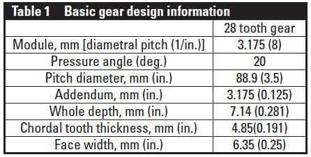
gears have a 1:1 ratio. Facility speed and torque can be varied as
needed during a test. The basic gear design information of the
tested gears is listed in Table 1.
As previously mentioned, the facility went through an evolutionary
period (Ref. 5) where shrouding, visual access, gearbox
lubricant removal, and instrumentation were added to the test
section . A photograph of the current test gearbox arrangement
is shown in Figure 3.
_400.jpg)
Figure 3 Current test gearbox arrangement utilizing shrouds (bottom
exit shown).
- Click image to enlarge
Static shroud thermocouples were utilized during all tests.
High-temperature glass was also utilized as the outside shroud
to encase the gears. Ballistic plastic and another layer of hightemperature
glass provided visual (and video) access to the gears
during operation. Lubricant for normal operation was fed at the
into-mesh location through part of the shroud (Fig. 4). The normal
operational flow rate was approximately 0.42 l/min (0.11
gpm), at 207 kPa (30 psig) jet pressure, with the lubricant inlet
temperature of ~110°C (230°F). Instrumentation and normal
lubricant jet locations are shown (Fig. 4). A turbine engine with
drive system lubricant MIL-L-85734 was used during the testing
at hand.
_400.jpg)
Figure 4 Example of test gear arrangement with outer gearbox cover removed, top exit shrouds shown.
- Click image to enlarge
Testing Methodology
Prior to the reported loss-of-lubrication testing, the gears were
broken-in to allow normal run-in wear to occur. The gears were
operated for at least 1 hour at ~50 percent maximum torque and at
full facility speed (10,000 rpm). After this period the load was then
increased to the maximum load and run for at least several more
hours prior to conducting a loss-of-lubrication test. Most tests
were run until the teeth failed to continue to carry torque (plastically
deformed), or were stopped just prior to this condition.
During all tests the static instrumentation and live video were
carefully monitored. Data from all sensors were collected at 1
Hz and stored for post-processing.
Testing and Discussion of Results
The test results described in this report were from the same
lot of gears manufactured to the basic gear design information
provided in Table 1. The gear material was an aerospace gear
steel (Ref. 9) that was carburized and final-ground; the surface
roughness was 0.41 micro-meters (16 micro-inch) or better. The gears have some tip relief starting at the highest point of singletooth
contact and a small amount of crowning across the face
width that is symmetric.
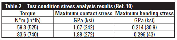
Five test results are described in this report. The tests in the
loss-of-lubrication condition were conducted at one of two load
levels, and are documented in Table 2. The basic gear design
information, along with the load level, produced maximum levels
of bending and contact stress, found via the analysis technique
in Reference 10.
An example of each of the two load levels will now be
described.
At the lower level of the two loads, two tests were conducted
with the loss-of-lubrication time of 40.8 and 43.1 min in length.
The data from the static thermocouples imbedded in the shrouds,
along with other facility temperatures, is shown in Figure 5.
_400.jpg)
Figure 5 LOL (loss of lubrication) data for 1.72 kPa (250 psi) load
pressure ~ 59.3 N*m (540 in*lb) torque tested at 10,000 rpm.
- Click image to enlarge
_400.jpg)
Figure 6 Post-test condition of the gears (gearbox cover and outer
high-temperature glass removed).
- Click image to enlarge
The gears in the post-test condition are shown in Figure 6.
Note that the test was conducted until the gear tooth meshing
heat generation and resultant temperature were high enough to
plastically deform the gear teeth. This type of post-test condition
occurred whenever the test was permitted to continue until
total loss-of-torque-delivery was achieved; a typical loss-oflubrication
failure at this condition is shown (Fig. 7).
_400.jpg)
Figure 7 Example of loss-of-lubrication test during final seconds of
operation.
- Click image to enlarge
_400.jpg)
Figure 8 Loss-of-lubrication data from higher load test 83.6 N*m (740
in*lb).
- Click image to enlarge
Two other tests were conducted at an elevated level of load,
i.e. — ~83.6 N*m (740 in*lb). These tests, in the loss-of-lubrication
mode, produced failures in 7.9 and 9.2 minutes. The test
temperature data from the 7.9-minute loss-of-lubrication test
is shown (Fig. 8). As can be seen from this data, the temperature
did not reach an increased steady-state condition prior to
increasing to failure, as it did in the test shown in Figure 5. After
the primary lubrication system was disconnected, the temperature
just continued to rise. The post-test condition of the test
gears is shown (Fig. 9) with the gearbox cover removed.
_400.jpg)
Figure 9 Post-test photograph of increased load test gears with outer
shroud high-temperature glass fractured.
- Click image to enlarge
Instrumented Gear Test
The most desired test for loss-of-lubrication behavior includes
employing on-component information. While it would be of
great benefit to have instrumentation at the gear-meshing sur-face, this has been shown to be very difficult to accomplish.
Even with full elastohydrodynamic film, the lubricant viscosity
of turbine engine lubricants — as used in rotorcraft drive systems
— is insufficient to develop films thick enough to keep the
on-surface instrumentation from wearing away. Therefore thermocouples
were installed at locations in areas of the gear where
contact does not occur.
The gear used in these tests is shown (Fig. 10); it is the gear
that was installed in the left side of the gearbox. The left-side
gear acts as the driving gear of the test section of the facility.
A total of five thermocouples were attached to the gear at: the
tooth tip mid-face width; root mid-face width; on the side of the
gear at the pitch radius; root radius; and mid-web locations. As
shown (Fig. 10), the thermocouple wires were covered by a thin
metal foil that was spot-welded to the side of the gear to protect
the instrumentation during operation. The rest of the required
hardware is shown (Fig. 11) prior to installation in the test rig;
the assembly in the test rig is shown (Fig. 12).
_400.jpg)
Figure 10 Instrumented LOL test specimen before testing.
- Click image to enlarge
_400.jpg)
Figure 11 Loss-of-lubrication test specimen and related components.
- Click image to enlarge
_400.jpg)
Figure 12 Test set-up for instrumented test gear.
- Click image to enlarge
The initial data for warm-up and operation of the facility
in the normal-to-loss-of-lubrication mode is shown (Fig. 13).
_400.jpg)
Figure 13 On-gear and out-of-mesh thermocouple data from start-up to
instrumentation failure during loss-of-lubrication.
- Click image to enlarge
During this same test the lubricant was shut off and the test run
until failure. The data from loss-of-lubrication initiation to failure
for the shroud (static) and other facility thermocouples is
shown (Fig. 14).
_400.jpg)
Figure 14 Data from shroud and facility (static) thermocouples.
- Click image to enlarge
The data in Figures 13 and 14 indicate that the bulk temperatures
of the gear were exceeding the temperature that was found
from the static shroud thermocouples. In the normal lubrication
condition this value was 20 to 40°F — depending on the location.
In loss-of-lubrication mode this amount was as much as 500°F
higher on the gear than that of the static shroud thermocouples.
In Figure 13 the data beyond 8,200" is believed to be invalid due
to post-test inspection of the thermocouple wiring that was melted
together at the common locations through the shaft. The thermocouple
wiring coating was exposed to bulk temperatures in the
gear beyond the melting point of the wire coating.
The post-test condition of the gears used in this test is shown
(Fig. 15). What can be noted is that a bending failure occurred
before the loss-of-lubrication test — as the failed tooth has no
evidence of running in this post-test condition. A hypothesis
is that tooth failure was initiated by a spot-weld in the root fillet
region from the thin metal protection strap that was used to
cover the thermocouple wiring.
_400.jpg)
Figure 15 Post-test condition after loss-of-lubrication test was
completed. Gearbox housing, slip ring and outer high
temperature glass removed.
- Click image to enlarge
_400.jpg)
Figure 16 Instrumented spur gear post-loss-of-lubrication test condition.
- Click image to enlarge
In Figure 16 the tooth that failed in bending shows no apparent
damage from loss-of-lubrication, since it occurred before
this lubrication condition was initiated. Upon closer examination,
the thin metal strapping used to overcoat the wiring that
was spot-welded to the tooth was found to be the initiation site
of the bending failure. Future testing of hardware for this purpose
will not have this as a hold-down feature for the tooth
root-fillet area.
Conclusions
A series of five loss-of-lubrication tests were conducted in an
aerospace-simulated environment using consistent sets of test
hardware. Following is a summary of the test results:
Applied torque can have a drastic effect on loss-of-lubrication
time. An increase of torque by 40%, 59.3 to 83.6 N*m (525 to
740 in.-lbs), resulted in a decrease in loss-of-lubrication operation
time by 75% (42 to 8 min).
Operation in loss-of-lubrication mode at lower torque produced
an elevated steady-state temperature condition. The higher
torque level did not have this operating time at an elevated
steady-state temperature condition. During the higher torque
tests the temperature continued to increase until failure of the
teeth.
On-component thermocouple data revealed that the gears
under normal conditions have bulk temperatures that are 20 to
40°F higher than the fling-off temperatures measured by the
static shroud thermocouples.
On-component thermocouple data indicated that during
loss-of-lubrication, conditions bulk temperatures on the gear
are from 150° to 500°F higher at certain times during this test
mode, when compared to the static shroud temperatures.
References
- ADS-50-PRF. “Aeronautical Design Standard, Rotorcraft Propulsion
Performance and Qualification Requirements and Guidelines,” U. S. Army
Aviation Troop Command, April 1996.
- Handschuh, R. “Thermal Behavior of Spiral Bevel Gears,” NASA–
TM-106518, ARL-TR-403, January 1995.
- Morales, W. and R. Handschuh. “A Preliminary Study on the Vapor/Mist
Phase Lubrication of a Spur Gearbox,” NASA TM-1999-208833, February
1999.
- Morales, W., R. Handschuh and T. Krantz. “Feasibility Study of Vapor-Mist
Phase Reaction Lubrication Using a Thioether Liquid,” NASA/TM—2007-
215035, December 2007.
- Handschuh, R., J. Polly and W. Morales. “Gear Mesh Loss-of-Lubrication
Experiments and Analytical Simulation,” NASA/TM—2011-217106,
November 2011.
6. Oswald, F. “Mechanical Components Branch Test Facilities and Capabilities,”
NASA/TM—2004-212722, January 2004.
- Krantz, T. and A. Kahraman. “An Experimental Investigation of the Influence
of the Lubricant Viscosity and Additives on Gear Wear,” NASA/TM—2005-
213956, ARL-TR-3126, October 2005.
8. Krantz, T. “The Influence of Roughness on Gear Surface Fatigue,” NASA/
TM—2005-213958, October, 2005.
- Pyrowear Alloy 53. Carpenter Technology Corporation, AMS 6308B.
- Vijayakar, S. and S. Abad. Helical 3-D User’s Manual, Advanced Numerical
Solutions, Hilliard, OH, February 2005.
About Author
Dr. Robert F. Handschuh has over
30 years of experience with NASA and
Department of Defense rotorcraft drive
system analysis and experimental methods.
He has served as the Drive Systems team
leader for the Tribology & Mechanical
Components Branch at NASA Glenn
Research Center in Cleveland, Ohio for
over 15 years, and currently leads the research there in
high-speed gearing, including windage, loss-of-lubrication
technology, and hybrid gearing. Handschuh is credited with
successfully developing many experimental research test
facilities at Glenn, and has conducted testing in the following
areas: high-temperature, ceramic seal erosion; blade-shroud
seal rub; planetary geartrains; spiral bevel gears and face
gears; high-speed, helical geartrains; single-tooth-bending
fatigue; and high-speed gear windage.
Lucas J. Gargano is a NASA Glenn Research Center
LERCIP intern.


.jpg)
.jpg)
.jpg)
.jpg)
.jpg)
.jpg)
.jpg)
.jpg)
.jpg)
.jpg)
.jpg)
.jpg)
.jpg)
.jpg)
.jpg)
.jpg)
.jpg)
