If the stiffness of all these parts is much greater than that of the elements involved in meshing (teeth and gear blank stiffness), we can see and measure the phenomenon in its “pure” form. But if the parts of the test rig have stiffness of the same magnitude, many effects mix together and influence the final measure. Thus the results are not easily interpreted, and the TE is difficult to evaluate quantitatively.
A test rig specifically designed to measure TE has been constructed by the authors, with the aim of obtaining the maximum stiffness compatible with the dimensions of the layout of the test rig. Its features are described in Reference 7. The most important characteristics are the following:
• Three-phase asynchronous motor controlled by inverter, with maximum power of 100 kW, maximum torque of 500 Nm and maximum speed of 3,800 rpm.
• Two eddy current brakes.
• Variable center distance of gears.
A schematic and photo of the test rig are shown in Figures 1 and 2. Gears are mounted overhung to allow a quick setup, but the overhang is kept as low as allowed by the gear face width and bearing dimensions. The shafts are supported by two heads, which can be positioned and adjusted in any direction on the support plane. In this way, it is possible to set the desired center distance, with the limits defined in the design step, and misalignments, both in the plane of the shaft axes and in the orthogonal one. The misalignment in the plane of the axes is driven by a pin centered on the gear middle face, while the misalignment in the orthogonal plane is set by means of shims; appropriate reference marks, machined during the manufacturing, allow an accurate measurement of the position.
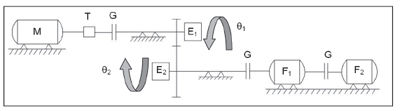
Figure 1--Schematic layout of the test rig for TE measurements: M = motor; T = torque meter; F1 & F2 = eddy current brakes; G = couplings; and E1 & E2 = optical encoders.
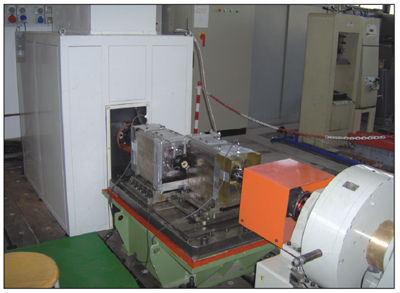
Figure 2--The test rig.
As explained in a previous paper (Ref. 8), the TE measurement system designed for this test rig is based on optical encoders, chosen for their high accuracy and preferred to other measurement systems based on radial and tangential accelerometers. The two encoders measure gear positions è1 and è2; these measurements, properly elaborated, let us calculate TE.
On the basis of the TE definition, its measure requires the independent measurement of the two angles è1 and è2. It is fundamental that errors and measurement uncertainty are lower than quantities to be measured. Since the TE of high-quality gears (those generally involved in applications which need this kind of measurement) amounts to seconds of a degree, the measurement system must have a higher degree of precision.
For this reason, two high-resolution Heidenhain encoders with 18,000 divisions have been chosen. The high number of angular divisions enables a high resolution. One angular division corresponds to 72" of degree, and it can be further divided if the acquisition system can identify, without aliasing, the sinusoid generated by the encoder corresponding to the passage of an incision. This involves an upper threshold of drive shaft angular velocity, which depends on the maximum acquisition frequency of the used data acquisition board. Signals are acquired along with a reference phasing signal, which enables the correlation of the angular positions of the two gears, which in turn allows the creation of TE diagrams, always starting from the same meshing teeth of pinion and wheel.
Experimental Results
Two series of experimental tests have been completed. In the first one, a gear set with profile modifications on pinion and wheel tooth tips (Fig. 3) has been tested. In the second one, a gear set having the same macro-geometry, but with an almost null profile modification on both pinion and gear (near to pure involute profile), has been tested (Fig. 4). Tables 1–3 report the macro-geometry data of both gear sets, which therefore differ only in profile modifications. TE and acoustic emission measurements have been performed for both gears.
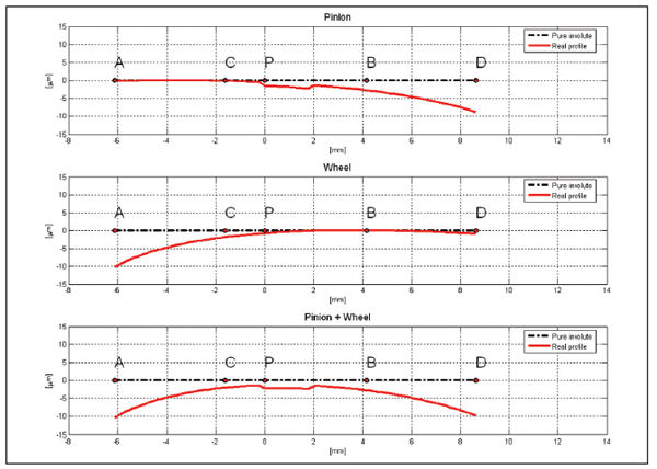
Figure 3--Profile modifications of the first gears.
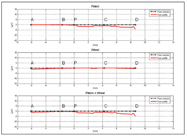
Figure 4--Profile modifications of the second gears.

The manufacturing process of the gears is the following:
1. Blank Turning.
2. Hobbing.
3. Case carburizing and case hardening.
4. Generation grinding.
5. Grinding of the hole and of the reference axial plane, with a single positioning on the machine and using the gear teeth as reference.
The signals are acquired by the two encoders and, after the elaboration of the signals by means of a specially developed software program, TE diagrams are calculated.
Figure 5 shows TE measured on the first gear set (with profile modification) as a function of pinion position and applied torque. We can clearly see that measured TE has the two typical components: a constant one, growing with the applied torque (because it corresponds to gear tooth mean deflection under load) and a variable one, corresponding to stiffness variation and manufacturing errors.
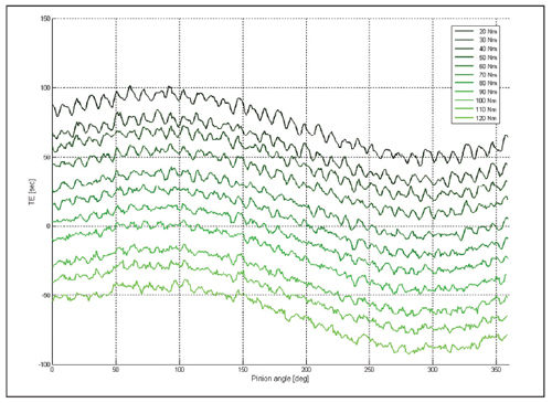
Figure 5--TE versus applied torque (first gear).
By virtue of a frequency spectrum that has been calculated for every TE measurement (Fig. 6), we can recognize the different components of the signal: the low-frequency harmonic (one per revolution) caused by gear eccentricity, the harmonic at mesh frequency with its multiples, and spectral components at lower frequencies than mesh frequency.
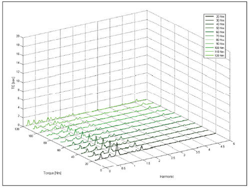
Figure 6--TE spectrum versus applied torque (first gear).
The amplitude of the first spectral component (mesh frequency) depends on applied torque, as we can clearly see in Figure 7. Therefore, an accurate study of profile modifications can reduce TE in correspondence with a chosen value of applied torque, reducing acoustic emission at the source.
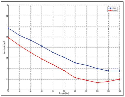
Figure 7--Spectral component of TE at mesh frequency versus applied torque (first gear).
Noise measurements on the same gear set considered for TE are shown in Figure 8. We can see a close correlation between sound pressure level (SPL) and TE in that the torque values that minimize TE also minimize acoustic emission.
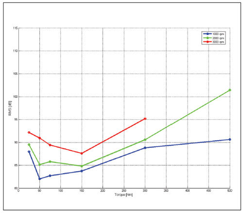
Figure 8--SPL versus speed and torque (first gear).
If we plot SPL spectrum at a given torque at different motor speeds (Fig. 9), we can see mesh frequency and its multiples shifting on the frequency axis. These diagrams are also called “waterfall” diagrams.
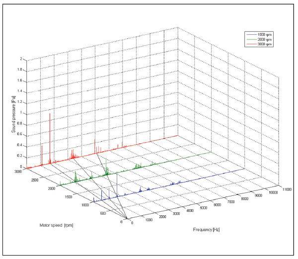
Figure 9--Sound pressure waterfall diagram (first gear).
By properly filtering the SPL signals (Fig. 10), we can highlight the phenomenon of sidebands, which consists of harmonics at the following frequencies:
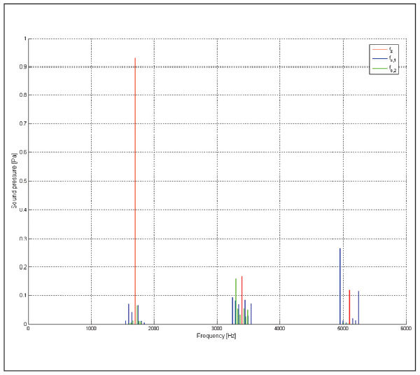
Figure 10--Sidebands (first gear).
where
fz = mesh frequency
fs,1 = input shaft frequency
fs,2 = output shaft frequency
The same measurement procedure has been applied to the second gear set, but with no profile modification. SPL values are shown in Figure 12. We can clearly see that acoustic emission increases linearly with applied torque, and its trend follows that of the amplitude of the harmonic at mesh frequency (Fig. 11), as observed for the first tested gear.
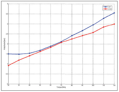
Figure 11--Spectral component of TE at mesh frequency versus applied torque (second gear).
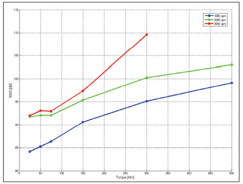
Figure 12--SPL versus speed and torque (second gear).
Conclusions
Measuring TE is necessary to validate profile modifications, defined during the design phase, in order to reduce acoustic emission. TE measurement is complex and requires an appropriate test rig; otherwise experimental results can be influenced by other phenomena, which can hide the component due to tooth deformation.
On the basis of an accurate analysis of the experimental results—and with the help of theoretical simulations—profile modifications can be improved, allowing for a solution that minimizes TE at the desired torque.
A mix of theoretical simulation and experimental validation seems to be the right way to design quieter gears and transmissions.
References
1. Munro, R. G. and N. Yildirim, “Some measurements of static and dynamic transmission errors of spur gears,” International Conference on Gears, Newcastle, 1994.
2. Walker, H., “Gear Tooth Deflection and Profile Modification. Part 1,” The Engineer, p. 409–411, October 14, 1938.
3. Walker, H., “Gear Tooth Deflection and Profile Modification. Part 2,” The Engineer, p. 434–436, October 21, 1938.
4. Walker, H., “Gear Tooth Deflection and Profile Modification. Part 3,” The Engineer, p. 102–105, August 16, 1940.
5. Dudley, D. W., “Modification of Gear Tooth” Product Engineering, p. 126–131, September 1949.
6. Davoli, P., C. Gorla, F. Rosa, A. Castellini and V. Cometti, “L’errore di trasmissione: come si calcola, come si reduce,” Organi di trasmissioni, May 2001.
7. Davoli, P., C. Gorla, F. Rosa and G. Vergine, “Un banco prova innovativo per la ricerca sull’emissione acustica dei riduttori industriali” Organi di trasmissione, February 2003.
8. Davoli, P., E. Zappa, S. Biondo and E. Brambilla, “Misura dell’errore di trasmissione degli ingranaggi mediante encoder ottici,” Organi di trasmissione, January 2003.
9. Houser, D. “Gear noise,” Dudley’s Gear Handbook, 2nd edition, McGraw-Hill, 1991.
10. Diana, G. and F. Cheli, Dinamica e Vibrazione dei Sistemi, UTET, 1993.
11. Smith, J.D., Gear Noise and Vibration, M. Dekker, 1999.
12. Rossi, F., “L’Errore di Trasmissione degli ingranaggi cilindrici: calcolo teorico e misura sperimentale,” Degree Thesis, Faculty of Industrial Engineering, Politecnico of Milan, April 2006.
Piermaria Davoli (member AGMA, ASME, SAE) is a full professor of machine design at the Department of Mechanical Engineering, Politecnico di Milano (Italy). His research topics include gear transmissions, surface and bending fatigue of gears, and noise emission.
Carlo Gorla is an associate professor of mechanical design at the department of mechanical engineering, Politecnico di Milano (Italy). His research topics include gear transmission design, gear bending fatigue, gear noise emission and gear manufacturing.
Dr. Francesco Rosa is an assistant professor at the department of mechanical engineering, Politecnico di Milano (Italy). His research topics include methods and tools for geometric modeling of gears, simulations of manufacturing technologies, and simulations of component behavior in actual working conditions.
Fabrizio Rossi has a master of science degree in mechanical engineering and is a Ph.D. student at the department of mechanical engineering, Politecnico di Milano (Italy).
Giuseppe Boni is a senior gear designer at Dana Heavy Vehicle Technologies and Systems—Europe, located in Italy. He joined Dana in 2003, after working at ZF Marine.


