

What happens if science proves engineering wrong?
Scientists are trained to question everything, but what happens if a scientist proves a standard engineering practice to be wrong? Or to be more precise, when science finds a solution where engineering has none, but thinks it has one as the machines that produce gears seem to implicitly solve the problem for them. This despite the fact that spur gears are well know to be noisy and that this should be a warning sign that all is not well.
The short answer is that the engineers ignore it, even when the proof is easy to understand and validate. I will leave to you to consider the deeper meaning of this and instead just present you with the proof. The proof is easy to understand and no previous gearing knowledge is required.
Gears have been around for a very long time and they are used extensively in mechanics. Virtually all gears in use today are of the involute gear type. These involute gears have many advantages that I won’t go into here. But it is safe to say the engineers have put a lot of work into to getting it just right. Involute gearing is seen as a difficult dark art in engineering and few claim to really understand it. Instead engineers use many well-established formulas to calculate their gears (or most often just buy them ready-made).
In involute gearing everything is based on the so called “pitch circle”. This is the imaginary circle with which a gear rolls over the pitch circle of the other gear that it is intermeshing with. This seems like a reasonable starting point when designing a gear system. But from a mathematical point of view this starting point makes no sense.
Mathematically speaking the pitch circle is only something that is derived from the underlying structure, and it is this underlying structure that everything should really be based on. Involute gears use involute curves for the shape of their teeth and in gears all these involute curves start on the so called “base circle”. This base circle then, is what mathematically speaking all the formulas on involute gearing should be based on.
But before we deduct the formula, we can go even deeper.
The involute curve itself is often portrayed as a mathematical nightmare, but it too can be deeper analysed to reveal the very simple three-dimensional shape that it is actually based on. This shape is called the “3D involute shape”, and it can be generated by a straight line rotating around, and moving up, a cylinder at a constant rate. So let’s quickly explain this in detail before we go on.
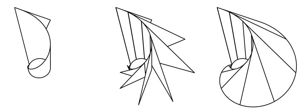
In the graph below we see twelve figures (for a video explaining more see: http://new-cvt.com). Starting with a simple triangle in the top left, and ending with an example of the so called “conical involute gear type” in the bottom right. Horizontal cross-sections of this conical involute gear type are the bases of all the two-dimensional outlines that form the bases of all the other involute gear types. Understanding this is the key to understanding a lot about involute gearing and involute intermeshing. The graph with twelve figures is self-explanatory, but note that figures six and seven show the 3D involute shape. And also note that any horizontal cross-section of this 3D involute shape shows the same involute curve, and that only the starting point of this involute curve on the cylinder changes.

So as you can see the involute curve always starts at some point on the cylinder at the centre of the 3D involute shape. And in two dimensions it is the horizontal cross-section of this cylinder that we call the “base circle”. This explains why mathematically speaking it makes so much more sense to base everything on the base circle rather than on the pitch circle. The pitch circle is depended on the pressure angle, which itself is depended on the vertical height of the cross-section through the basic conical involute gear.
Now let’s get back to deducting the formula.
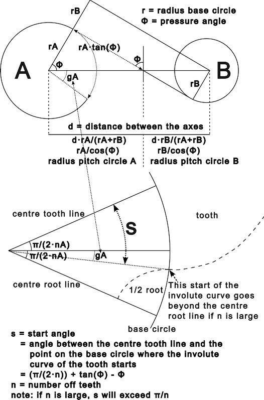
When calculating the exact shape of involute gears we need to know the exact position where each involute curve starts on the base circle.
A little research on the internet quickly reveals that there many different and mutually exclusive ways in use for calculating this position. All the authors are satisfied that their solution is good enough for what they need. Unfortunately I could not find any clear explanations as to why these solutions would be theoretically valid. It seems everybody is assuming that someone else has the answer and that engineering textbooks simply did not find this knowledge interesting enough to publish. However, true science wants to understand everything, so let’s go for theoretical perfection. It’s also a lot simpler.
When two gears intermesh with each other there is a point where the contact point between the teeth is exactly on the line between the axes of the two gears, the halfway point so to say. This is known as the “pitch point”. The top figure in the graph below shows a general representation of such a pitch point. This pitch point is very useful as it makes the maths a lot easier as it appears to be a situation of perfect symmetry.